
0 Illustrations
ASTOR PLANE; STOCKADE SYSTEM
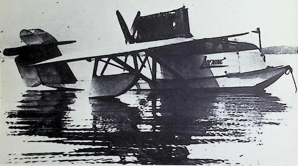
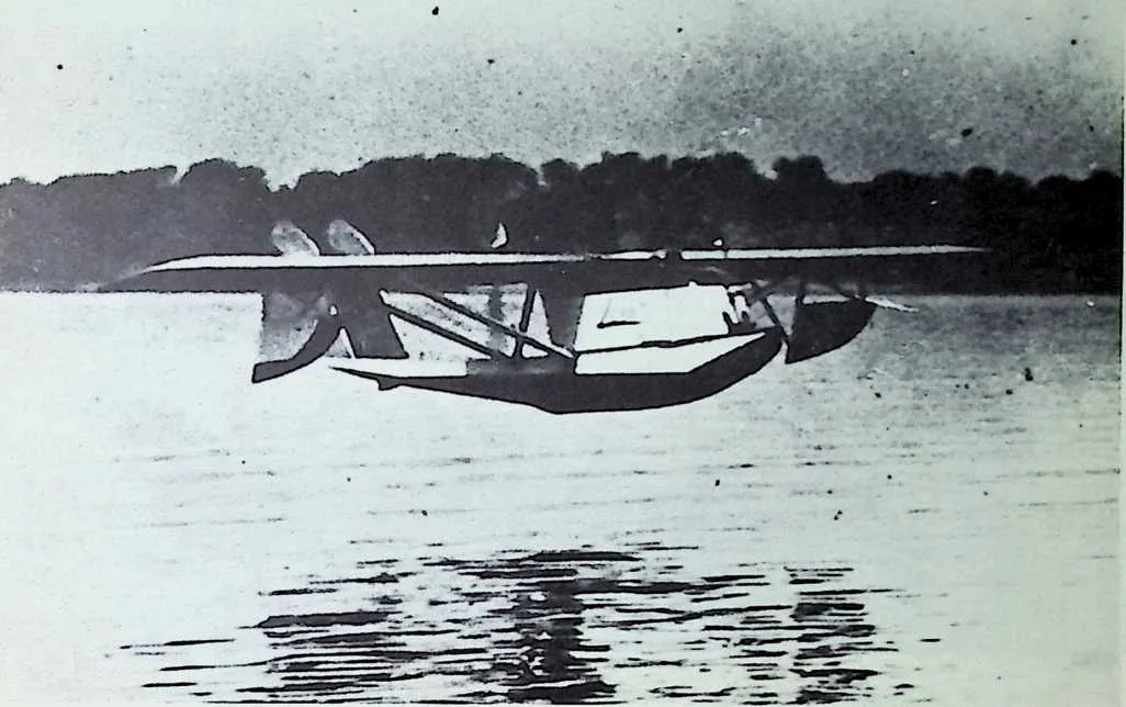
27-8 News item from the New York Herald, Sept. 29, 1922, reporting one of Fuller’s early aviation experiences, piloting Vincent Astor’s flying boat designed by Grover Loe-ning. This was the first monoplane flying boat. Fuller asserts that his 55 years of experience with ”ships of the sea,” and 42 years of experience with ”ships of the air,” account for his ”intuitive dynamic sense,” which he considers to be the ”self-starter of fundamental invention and design.’’ He feels that theoretical knowledge, no matter how profound, can never turn over the complex train of techno-scientific and economic gears, without whose reciprocal functioning inventions are ineffectual or abortive. He classifies ”ships of the sea’’ and ”ships of the air’’ as vessels or containers that are to be classified under the generic heading of ”environment controls.”
4 NEW YORK HERALD, FRIDAY. SEPTEMBER 29, 1922.
56-r ItaMelc *
7FullerS/in Astor’s Monoseaplane
8Fly to Bar Harbor in 4 3-4 Hours . picut. iff Buckminster Fuller of the i and then flew to Wiscasset, Me.. where Navnl Reserve, accompanied by Mrsi I they spent the right. Then they made Fuller, has just finished part of a vaca-1 flights around Bar Harbor and at other
9 lion cruise In Vincent Astor’s monoseaplane. and will return to New York to-day from. Bear Island, Me., and fir to Boston. There they will attend a wedding at which Lieut. Fuller will act as usher, and then-they will fly back to Olen Cove fdr another wedding on Sunday at 4 o’clock and one at Lawrence at 4:30. That night they will fly to New York so Lieut. Fuller can attend an ushers’ dinner.
10 The Fullers left New York last Wednesday In Mr. Astor’s flying boat. They went to Newport for two hours points along the Maine coast, stopping al Bear Island In Penobscot Bay. The trip from New York to Bar Harbor was made in four and three-quarters hours actual flying time.
11 Mr. Astor’s boat carries five passengers. Is equipped with 400 horse power Liberty motors, and can make 130 miles an hour. Lieut. Fuller, who Uvea on Long Island, served In the Navy during the war and Is now one of the most active officers of the Third Naval District. being In command of Eagle Boat No. 15, Naval reserve.
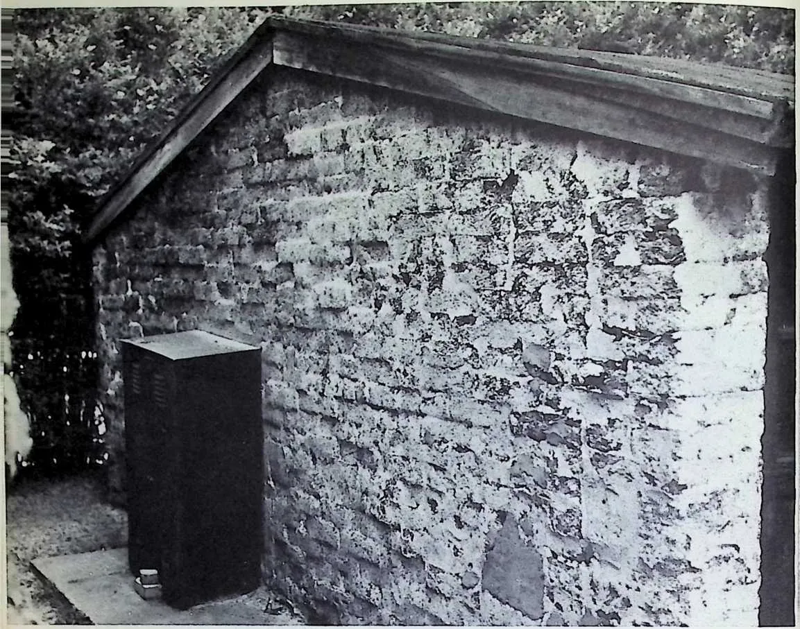
139 A garage wall made of Stockade Blocks still standing in Lawrence, Long Island, on the property originally owned by Fuller’s father-in-law, James Monroe Hewlett, co-inventor of the Stockade System and its manufacturing processes. (1923) Stockade walls were a system of reinforced concrete frame construction. The vertical frames were 4-inch columns on 8-inch centers. The cylindrical vertical 4-inch columns were tied together horizontally at every floor height by concrete lintels above and below every door and window opening. This continuous, integral concrete framing was poured progressively into tubular and horizontal space openings provided by 4-inch holes formed in the Stockade blocks which were 16 inches long, 8 inches wide, and 4 inches high, each with its two 4-inch vertical tubular holes on 8-inch centers. The Stockade blocks consisted of fibrous material such as excelsior or straw, bonded with magnesium-oxy-chloride cement. The fibers, impregnated by the cement, were blown into molds which felted them together. The 16 X 8 X 4 blocks weighed in the neighborhood of 2 pounds each; they were so light that they could be thrown to the second floor scaffolding, so tough that they would not break if they fell. The blocks were laid up dry; no mortar joint penetrated the wall. After completing their functions as molds for the concrete frame, they remained in place to serve as bonds for mortar and plaster, and subsequently as insulators for the wall. They provided insulation equivalent to 4 inches of cork. Interior and exterior walls thus formed seldom cracked, as they were independently bonded to the fibrous base, could expand and contract independently. The blocks were non-hygroscopic, consequently moisture was not drawn through the walls. Being petrified, they would not support combustion. Between 1922 and 1927, Fuller constructed 240 buildings in which the Stockade System was used. The structural system and stockade material was eventually sold to the Celotex Corporation, and may be frequently seen today in the form of an acoustical wall and ceiling material.
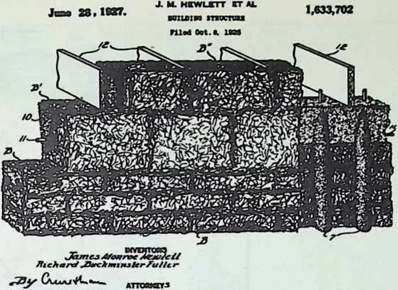
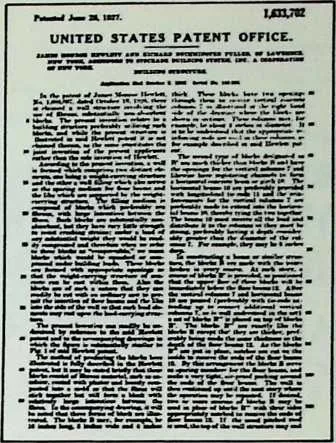
151610-11 Stockade Building System patent which was subordinate to Mr. Hewletts basic stockade wall patent. (1923)
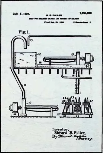
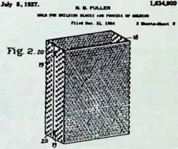
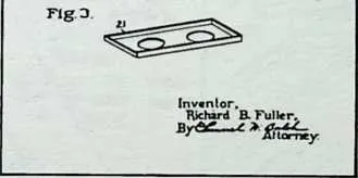
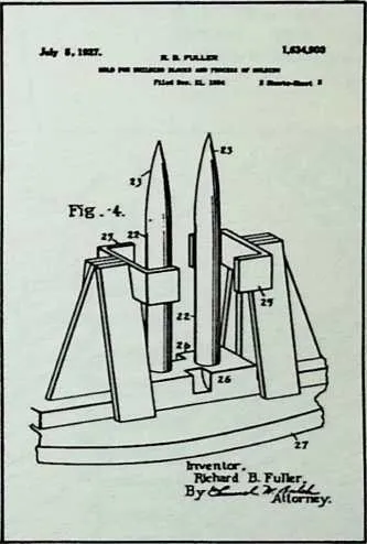

1912-15 Fuller’s Stockade Block manufacturing patent, covering a wet-fibrous, pneumatic, felting forming operation, many features of which have since been adopted in the manufacture of fiberglass resin products.
2122MULTIPLE-DECK 4D HOUSE;
23AIR OCEAN WORLD
- 16.
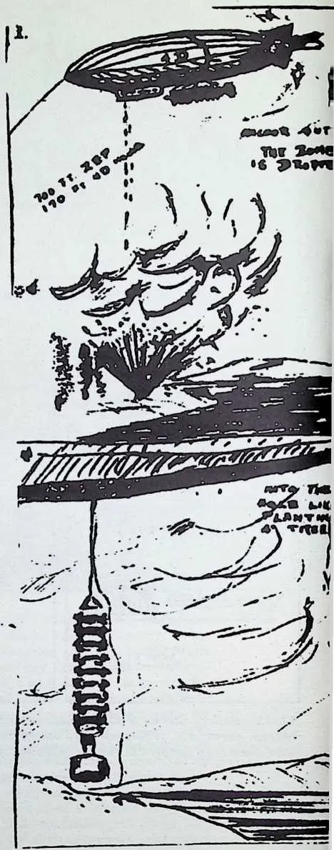
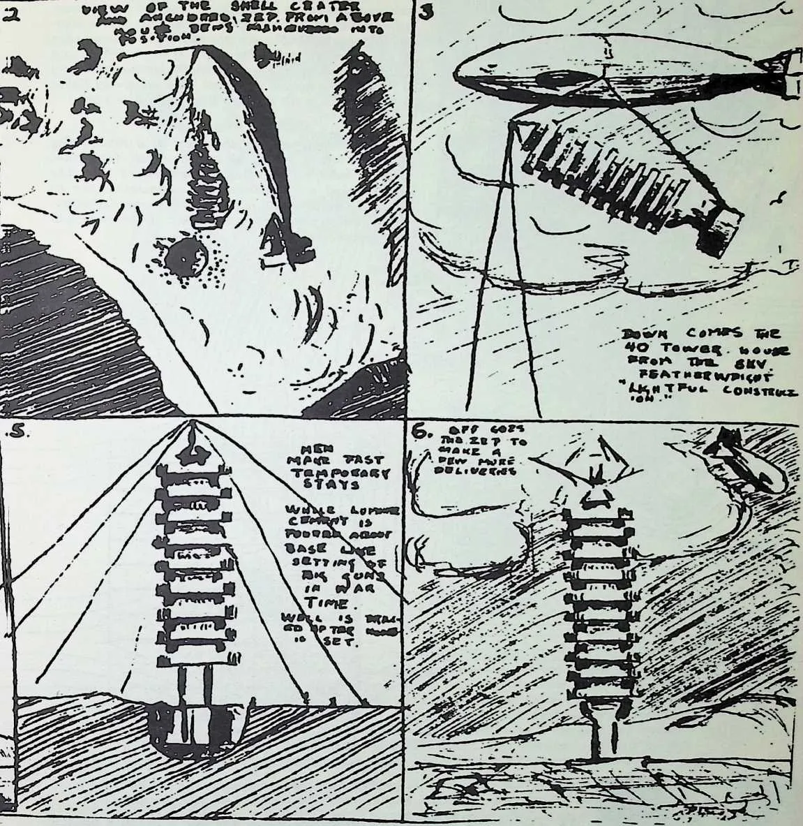
- Projected delivery by zeppelin of the planned 10-deck, wire-wheel, 4D tower apartment house. Fuller assumed that the dirigible, on approaching the site on which the house was to be erected, would throw out an anchor, then drop the bomb, creating by explosion the excavation to cradle the foundation. The 10-deck dwelling unit then would be lowered into the hole; the procedure, Fuller held, was ‘‘like planting a tree.” The structure was to be supported by temporary stays until cement, poured about the base line, hardened. (1927)
- 17.
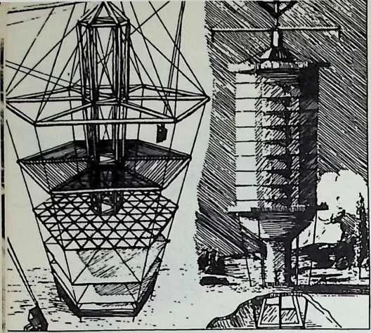 Variation of 10-deck house design, 1927, showing the three-way-grid
floor construction; pneumatic floor pads and their hard-shell covering;
balanced boom for raising and lowering construction units and heavy
pieces of furniture; tension cables; and septic tank. The hexagonal rim, to
which cables are attached, is the external edge of an all-around swimming
pool. At lower left, a unit bathroom (what was later to be the Dymaxion
bathroom) is shown being hoisted into place. This picture by Fuller was
published in the Chicago Evening Post in 1928.
- 18.
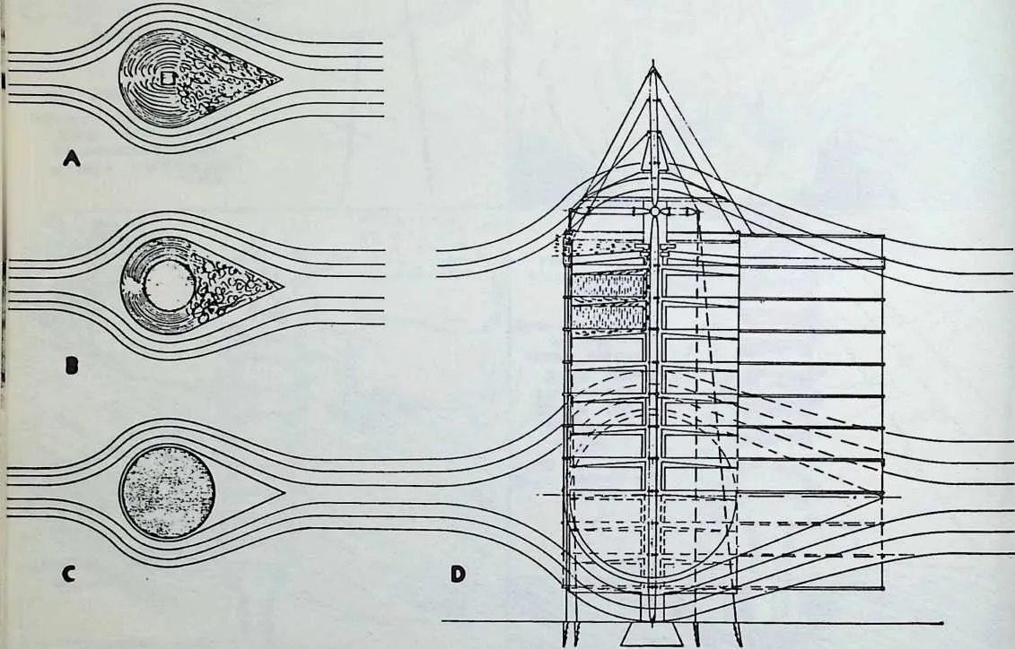 Diagrams illustrating the effect of a streamlining shield. At left are
typical air current effects: (a) a cube, (b) a cylinder, (c) an efficiently
streamlined unit. The cross-hatched areas indicate the comparative size of
structures which would have indentical wind resistance. At right: (d) is a
model of a 10-decked 4D structure with streamlined wind shield.
- 19.
 The 10-deck building with streamlined shield. The heat losses of
a building are proportional to the building’s air drag. Fuller observed
that a properly designed shield could reduce such losses to a negligible
quantity. He has always been concerned with what he calls ‘‘the invisible
behaviors of local environment-controlling structures.’’ Prominent in all
his environment control solutions are the invisible interior and exterior
aerodynamics of structures. In the design of the 4D 10-deck building, the
planned shield reduces the basic wind drag, hence reduces the necessary
structural size of the building. The shield thus permitted the design of
lighter structures, an essential factor in projected transportation by air.
(This picture is also shown on facing page of chapter on Nonconformity
and New England Conscience.)
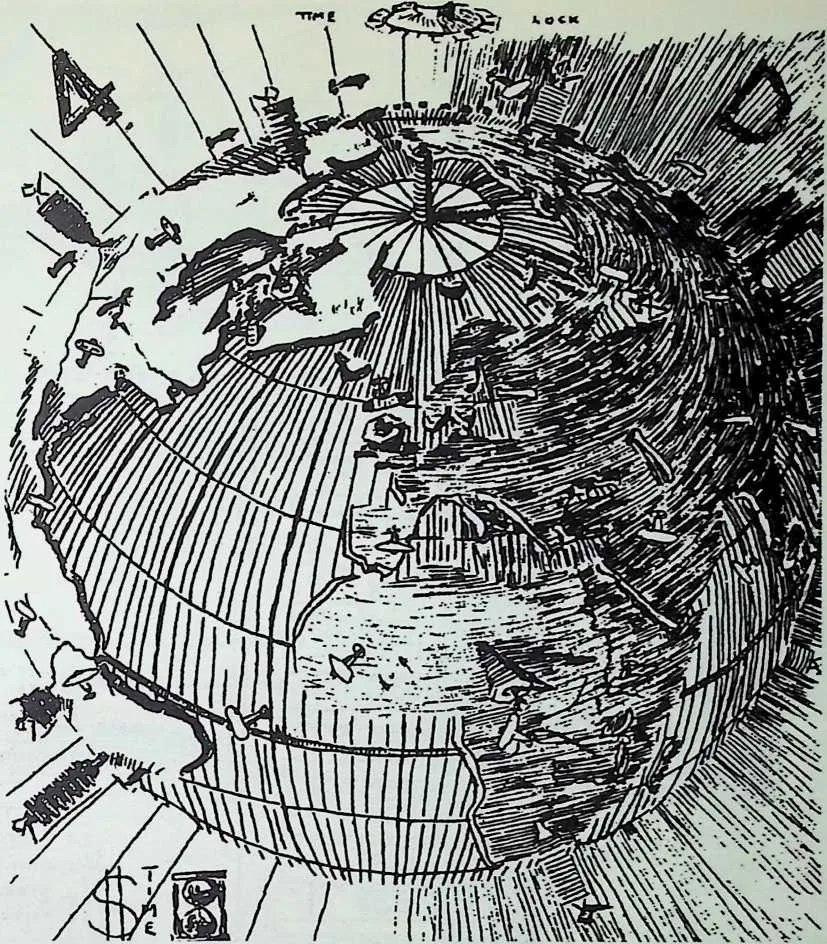
- 20.
- The Air Ocean World Town Plan, 1927, showing 10-deck 4D houses, which Fuller sometimes called ”stepping stone, world airline maintenance crew environment controls,’’ spotted around the earth in places where nature presented the most hostile conditions. Installation points, inaccessible to man in 1927, included the Arctic Circle, the Alaskan coast, Greenland, the Siberian coast, the central Sahara desert, and the upper Amazon. Great circle air routes, which in 1927 seemed dependent on such maintenance stations, were necessary to link the world’s population centers. This drawing pre-dates by five years any map showing great circle air routes. Fuller’s original 1927 caption read:
2626% of earth’s surface is dry land. 85% of all earth’s dry land shown is above equator. The whole of the human family could stand on Bermuda. AU crowded into England they would have 750 sq. feet each. ”United we stand, divided we fall’’ is correct mentally and spiritually but fallacious physically or materially. Two billion new homes will be required in 80 years.
27Feasibility studies showing that it was possible to have controlled environment in inaccessible places gave Fuller what he called a ‘‘technical permit’’ to preview a world integrated by air communications, hence a ”one-town world.’’ The ”environment control’’ structures were never built. It took the airlines many years to multiply the range of the airplane to the point where it could ‘‘jump the inaccessible places,’’ finally to establish world integrating potentials. Nevertheless, the development of the Air Ocean World Town Plan gave Fuller what he regards as a one-generation advantage in postulating an inherently integrated world, in contrast to the traditional ‘‘remotely divided world.’’
29 ffi
30 HtflS 4do SNAt MAST
31 MODEL
32 I PLANE.
33 SiiggMS
34MAST
35I.skyrnoMSHAo?
i PoiA/ER KA Dio
. QKiu. a BAR
36y Nursrry* sZ
37IO tuM
38 DlV/AUj DE<< 1, Pool
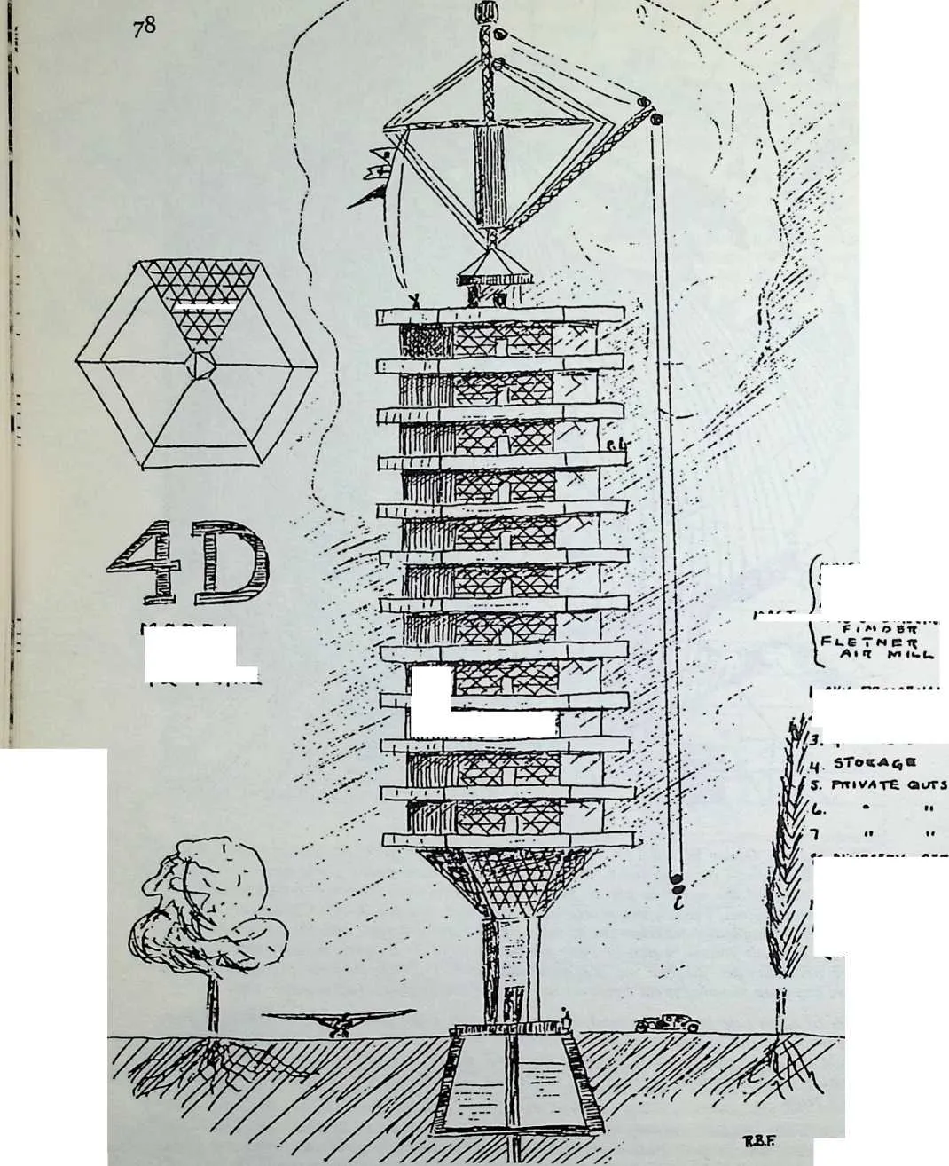
- 21.
- Twelve-deck version of the 4D multistory dwelling unit. Details show the hoist and signal mast, airplane beacon, Fletner air-rotor mill (wind operated power generator), sky promenade, living apartments, community facilities, diving deck, and swimming pool.
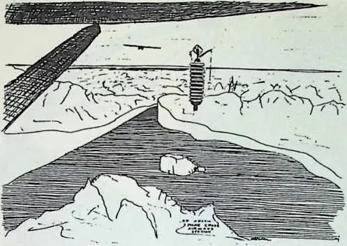
3922 Sketch by Fuller showing the hypothetical installation of a 4D multi-story dwelling unit near the North Pole. (1927)
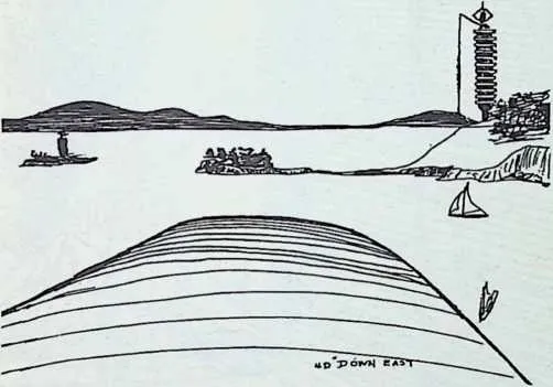
40 23, . . On the New England coast.
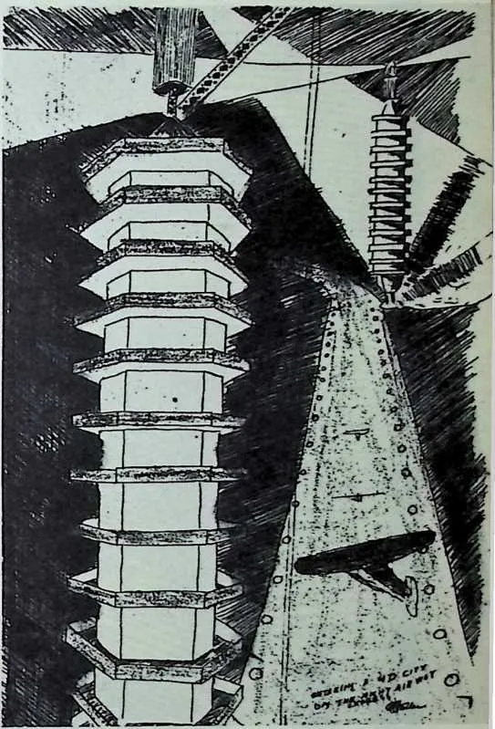
4125 4D sketch by Fuller: ”Entering a 4D city on the night airway express.” (1927)
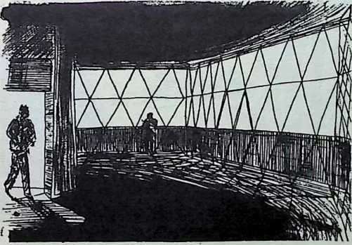
4324 Interior of the overhang deck in a 4D multi-story dwelling as shown in one of Fuller’s drawings on a mimeograph stencil. The cross-hatching represents triangular vacuum window plates.
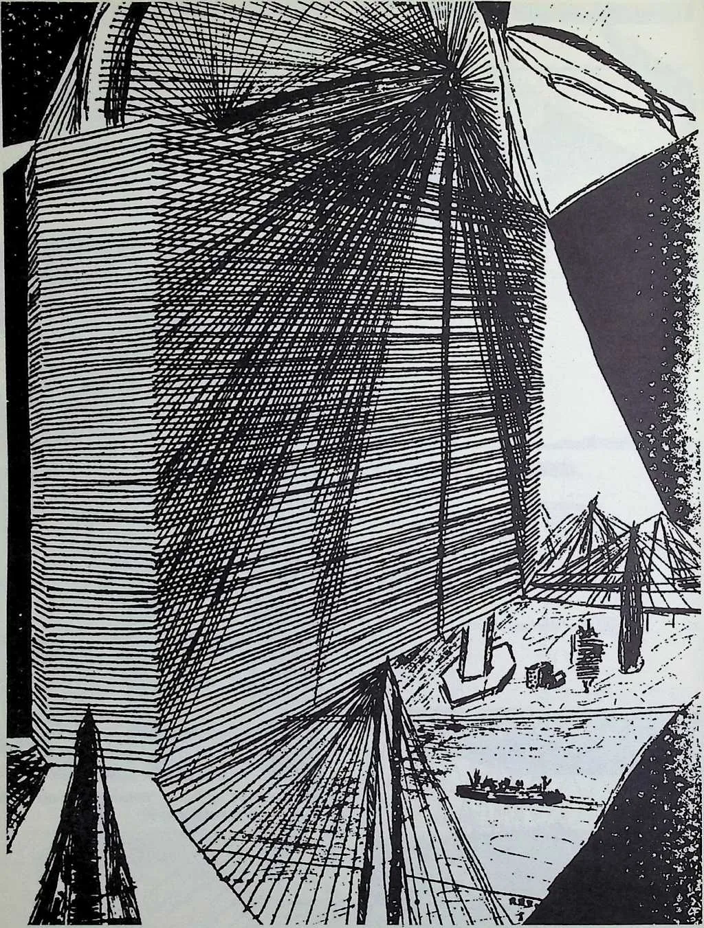
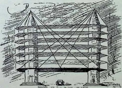
4426 Fuller’s projected loo-deck office building, which was combined with a suspension bridge whose masts curbed back on themselves like the rim of a wheel from whose hub the decks were suspended.
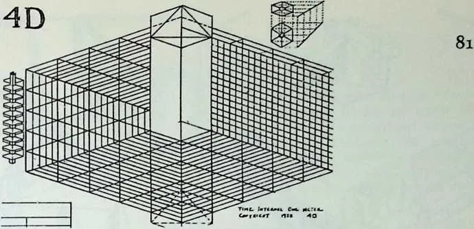
- 27.
- Coordinate system developed by Fuller to locate positions horizontally and vertically with respect to the space encompassed by the multi-deck structures. (1927)
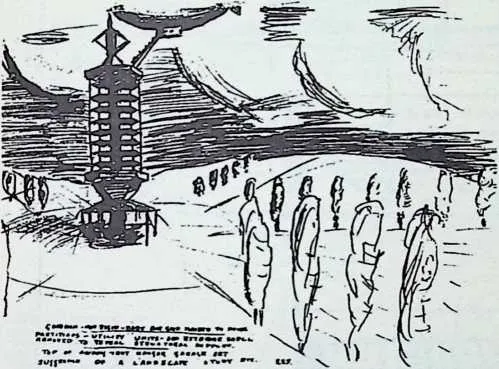
- 28.
- One of Fuller’s 1927 ideas was that the mast of the multi-deck house could be used as a dirigible mooring. Several years later, others, adopting this idea, proposed to use the tower of the Empire State Building for the same purpose.
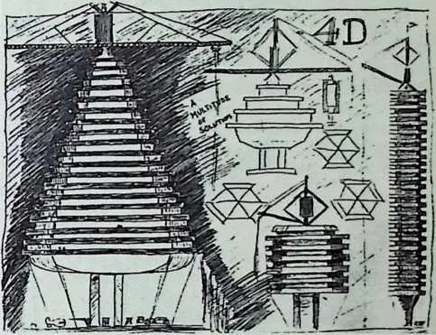
- 29.
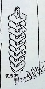
- Alternate forms of multi-deck 4D houses. Shown in the lower left corner is Fuller’s early conception of the 4D omni-directional transport.
48 30 Modified 4D twin tower office building.
50<OH3$T>hT WITH H O
51 use MET A U 09 FlUHE. ? ]
52Bit
53 SEE PATENTS Folt All? *
54 H’EATl’$ c ijrc u

- 31.
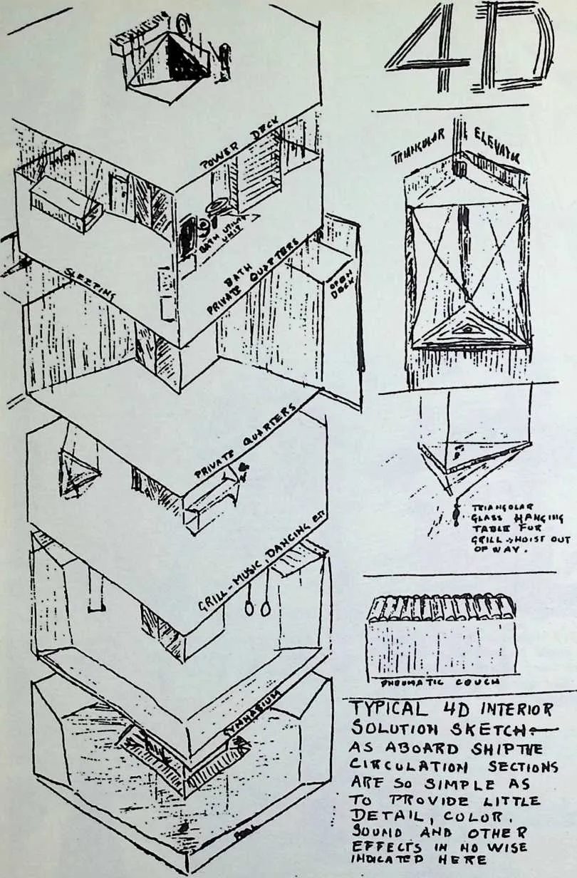
- Sketch by Fuller showing a cutaway view of typical interior sections surrounding the center shaft of the multi-story dwelling.
- 32.
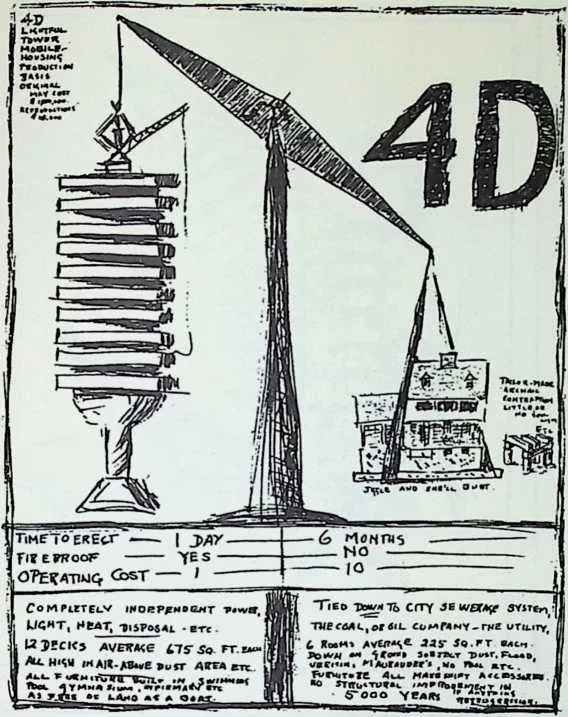
 Sketch and notes by Fuller dramatizing the advantages of his 4D
tower house as compared to a conventional 6-room house. (1927) The 4D
house was described as ”lightful; tower; mobile housing; production basis;
original may cost $1,000,000—reproductions $10,000.” Its advantages were
listed as follows:
56Completely independent power, light, heat, sewage disposal; 12 decks average 675 sq. ft. each; all high in air—above dust area, etc.; all furniture built-in; swimming pool, gymnasium, infirmary, etc.; as free of land as a boat; time to erect—I day; fireproof.
57The conventional house was characterized as a ”tailor-made archaic contraption with little or no sunlight; jiggle and she’ll bust.” Its limitations were described as follows:
58Tied down to city sewerage system, the coal, or oil company—the utility; six rooms average 225 sq. ft. each; down on ground subject dust, flood, vermin, marauders; no pool, etc.; furniture all makeshift accessories; no structural improvement in 5,000 years—if anything retrogression; time to erect—6 months; not fireproof.
- 33.
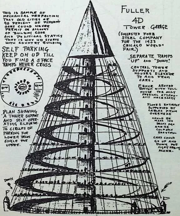
- Sketch by Fuller of 4D tower garage suggested as a steel company exhibit for the 1933 Chicago World’s Fair. (1927) The accompanying notes read in part:
59Fuller 4D Tower Garage. Plan showing a tower support and self-operating elevator to circles of parking.
60 SELF PARKING KEEP ON UP TILL YOU FIND
61 A SPACE RAMPS NEVER CROSS.
62Separate ramps for ”up” and ”down.” Central tower supports and houses elevator to and from cars. Fence around bottom with tollhouse —the only physical attendant necessary. Floors entirely supported by cables from overhead. Could be made 100 decks high and be colossally beautiful. Cars could go up and down for sightseeing alone.
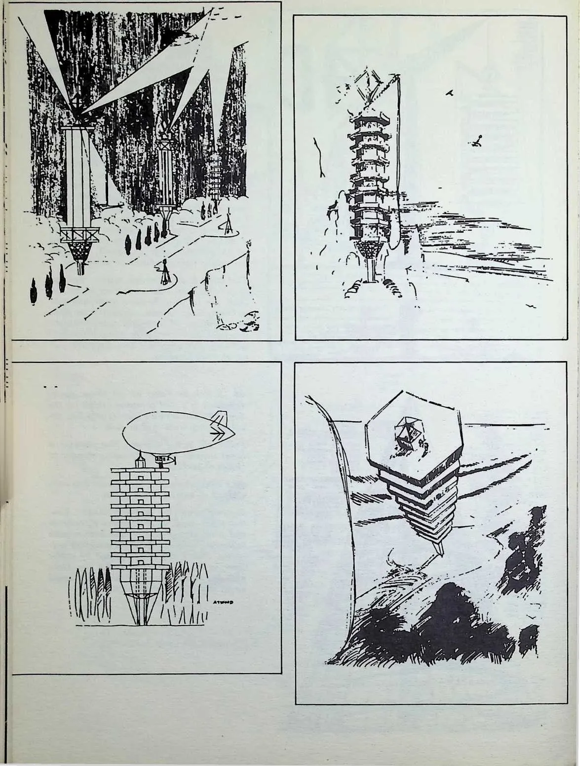
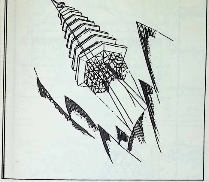
6534-39 Sketches by Fuller’s draftsmen arid students, 1927–28, showing various types and operations of 4D multi-deck houses. Shown in most of the sketches is the triangulated tension network which formed the shell that comprised the swimming pool as the lower component of the tower structure. This triangular comprehensive tension principle is akin to the pattern used in Fuller’s geodesic structures, initiated some 40 years later.
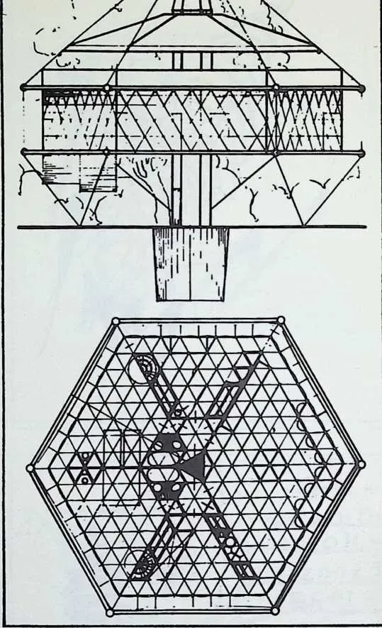
DYMAXION HOUSE
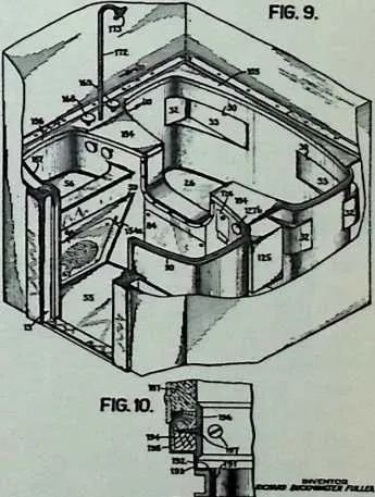
6840 Elevation and floor plan of the 4D Dymaxion House; 1928.
69Fuller calls this the ”clean-up model’’ of two earlier versions, the first of which was published in the magazine, Architecture, in 1928.
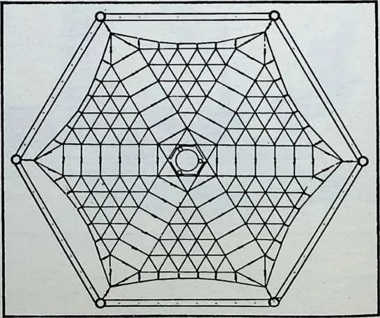
7041 The first Dymaxion House deck-tensioning pattern, 1927–29. Pneumatic bladders were to be laid in between the top and bottom cable network and tiedin like a bale of hay. Over this there was to be a hard shell floor.
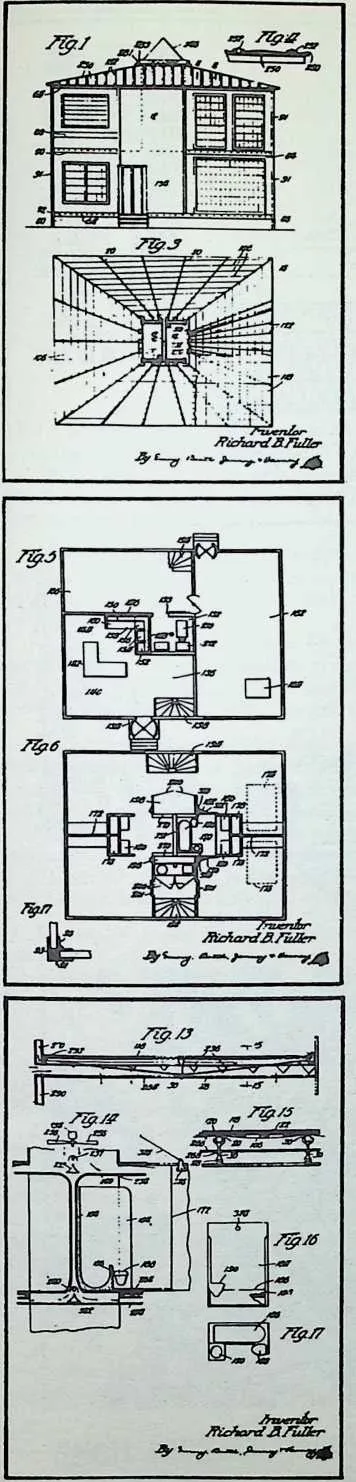
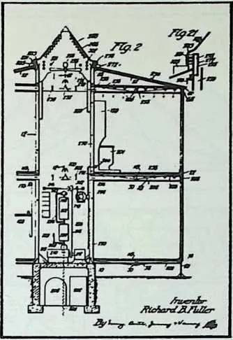
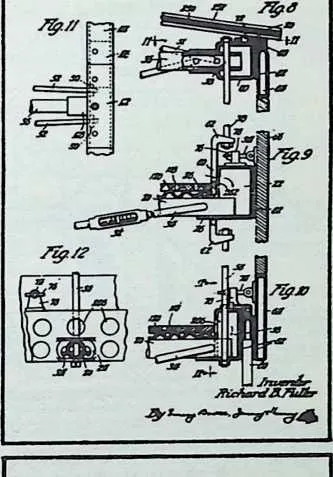
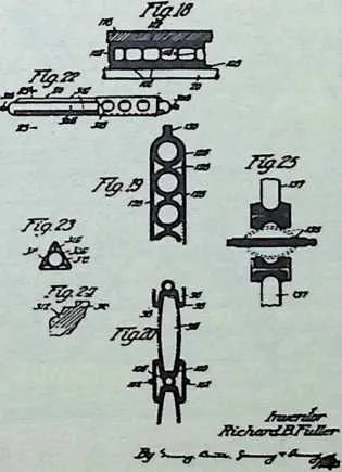
7242-47 The original 4D House patent drawings, 1927. These show the structure to be hung from a central mast, within which are located the heating, lighting, and plumbing manifolds. The heating and lighting are distributed from the mast to the surrounding rooms through the hollow ceilings in which are placed the appropriate reflectors and deflectors. Though Fuller’s preferred use of his invention was in the hexagonal plan, following his attorney’s advice his patent indicates that the system could also be used to provide a conventional box-like structure. The claims apply to any type of wire-wheel-like structure hung about a mast. Note in the patent drawings that (i)the foundation houses the water, septic, and fuel tanks; (2) the bathrooms and kitchen facilities do not rest oil a floor, but are suspended from the upper boom; (3) all rigid supporting structures are thin aluminum tubes filled with air—true pneumatic structures; (4) the windows are vacuum flasks set in air-tight gasket locks.
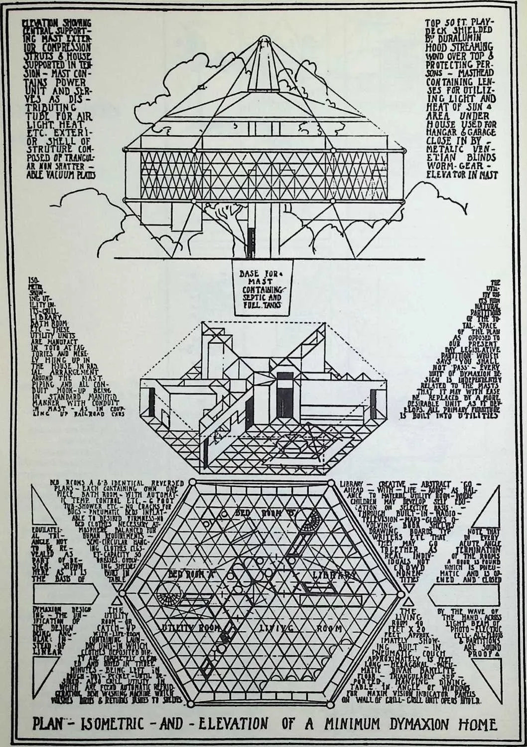
- 48.
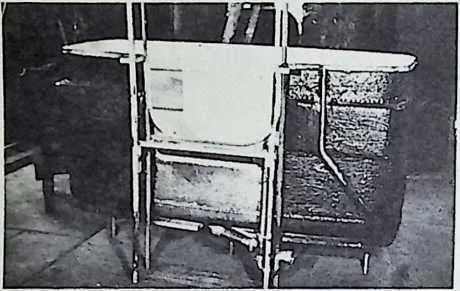
- Plan, isometric, and elevation of what Fuller, in 1927, conceived as a minimum 4D Dymaxion house. Although many of these items seem obvious and familiar today, none could be found in the architectural and home journals of 1927. Fuller’s original 1927 captions, published with this picture in 1929 by the Harvard Society for Contemporary Art, read as follows:
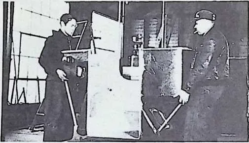
- 1.
- Elevation showing central supporting mast, exterior islanded compression struts, & house supported in tension. Mast contains power unit and serves as distributing tube for air, light, heat, etc. Exterior or shell of structure composed of triangular non-shatterable vacuum plates.
74Top 50-ft. playdeck shielded by Duralumin hood, streaming wind over top and protecting persons. Rain drained to central down-pipe through heated mast. Masthead containing lenses for utilizing light and heat of sun. Area under house used for hangar and garage, closed in by metallic Venetian blinds. Worm gear elevator in mast.
- 2.
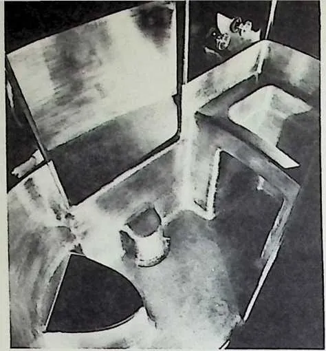
- Isometric, showing utility units, grill, library, bathroom, etc. These utility units are manufactured in toto at factories and merely hung up in the house in radial arrangement around the mast—piping and all conduit hook-up being in standard manifold manner with conduit in mast—as in coupling up railroad cars.
75The utility units form natural partitions of the total space of the plan as opposed to our present day legislative partition which says ”you shall not pass.’’ Every unit of
76Dymaxion design is independently related to the masts that it may with ease be replaced by a more desirable unit as it develops. All primary furniture is built into utilities.
- 3.
- Bedrooms A and B identical reversed plans, each containing its own one-piece bathroom, with automatic temperature control, etc. No cracks for bugs. Pneumatic beds inflatable to desired firmness. No bedclothes necessary. Atmosphere balanced for human requirements. Semi-circular clothes closet capacity: 50 dresses. Revolving shelves. Built-in table.
77The utility room, or catch-up-with-life room, containing laundry unit in which clothes deposited directly are completely cleaned and dried in three minutes, being left in roughdry pocket until desired. Also grill utility in which are found automatic refrigeration, dish washing machine which washes, dries and returns dishes to shelf.
78Library—abstract ”Go-Ahead-With-Life-Room”—as balance to material utility room—where children may develop self-education on selective basis through built-in radio-television, maps, globes, revolving book shelves, drawing boards, typewriters, etc., that they may go together as real individuals, not crowd nonentities.
79The living room, 40 feet by 20 feet approximately, showing built-in pneumatic couch, approximately 15 feet long, hexagonal pneumatic divan, bakelite floor, triangularly supported hanging dining table in angle of windows for maximum vision. Indicator panels on wall of grill. Grill units open into living room.
80Equilateral triangle not to be revealed as part of design. Shown here as it is the basis of Dymaxion designing—the unification of the design being angular instead of linear.
81Note that in every acute angle termination of the rooms, a door is found which is pneumatic and is opened and closed by the wave of the hand across light beam of photoelectric cell. All floors and partitions are soundproof.
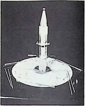
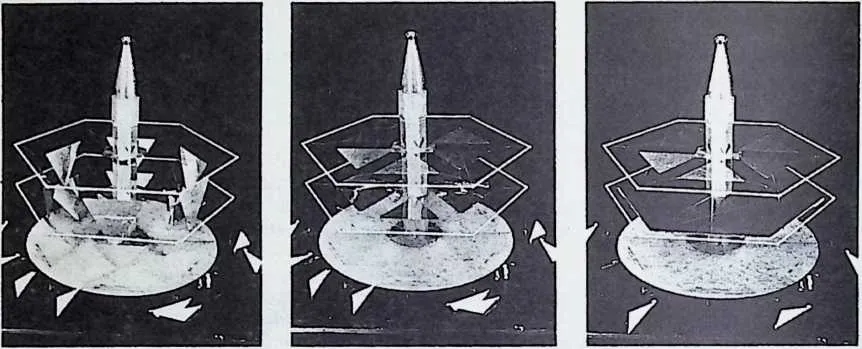
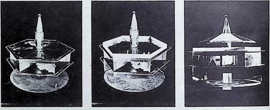
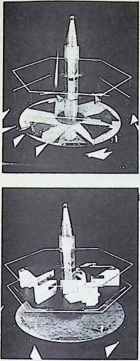
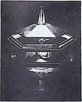
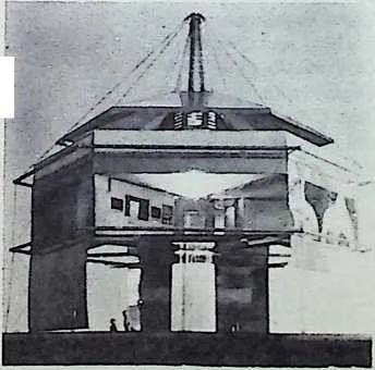
8449-59 Sequence pictures showing erection of the 4D Dymaxion house. Note that the structure is assembled from the top down. The house is essentially a wire wheel turned on its side, with the hub extended to become the mast. The compressional mast is islanded from the compressional ”atoll’’ rim by the tensioned web (the cables or ”spokes’’). This compression-tension patterning accounts for the integrity of the structure, tension providing the over-all structural coherence. (Fuller speaks of a structure, as a ‘‘regenerative pattern integrity.’’)
85When a wire wheel is turned on its side, another wire wheel, also on its side, can be superimposed, hub end to hub end. Fuller’s 10-deck building, or a 100-deck building, could be constructed by stacking wire wheel on wire wheel. Fuller observed, however, that a stack of wheels could be ‘‘knit” together in a unit axis of hub alignments by three sets of exterior, crisscrossed, triangular tension lacings, permitting the elimination of many of the interior sets of tensional spokes within the stack. The 4D Dymaxion house consisted of two such wheels. (1927)
- 49.
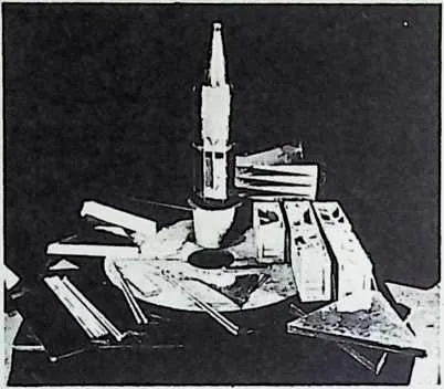
- Scale models of component parts of the 4D Dymaxion house, shown as they would appear when delivered to house site, ready for assembly.
- 50.
- The duralumin mast set in its foundation. Booms will be attached to the upper and lower hexagonal plates.
- 51.
- The wire wheel structure formed by floor beam tube held in tension by cables pulling from the mast-hub.
8652–53 Floorplates are strung into place, tensionally laced between the hub and rim of the ‘‘wire wheel.”
- 54.
- A hard shell placed over pneumatic bladder supports completes the floor assembly.
- 55.
- Utilities are swung into position, being supported by cable from the upper deck. Die-stamped bathrooms are in place, against mast. The utilities serve as space dividers; the 4D Dymaxion house required no wall partitions.
- 56.
- Ceiling units, connecting to mast, serve as distributors of light and air. Doors, operated by photo-electric cells, are shown at each vertex of hexagonal floor.
- 57.
- Transparent plastic, external wall plates have been installed and their triangular aluminum sheet camera shutter type roll curtains, and the roof deck and railings completed. The woman lying on the pneumatic bed is shown nude to dramatize the fact that within the house, temperature, humidity, and air flow are maintained at optimum levels, making clothing and bed covering unnecessary.
8758–59 The house is completed when the Duralumin hood is suspended from the central mast. Night scenes show effect of central lighting system, located in the mast; light is reflected and diffused throughout the house.
- 60.
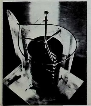
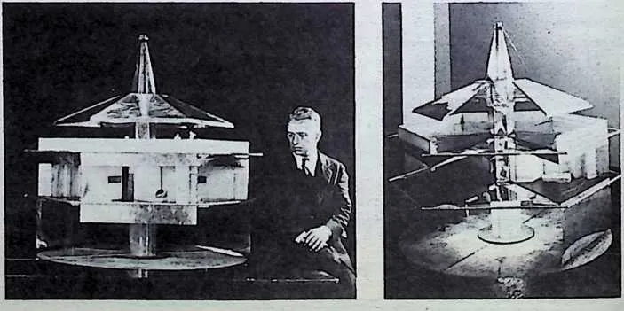
- Portrait of Fuller, 1927, with completed model of the 4D Dymaxion house. The house, as planned, was to have a total weight of 3 tons, including all equipment, and to encompass an interior floor area of 1600 square feet.
- 60.
- Portrait of Fuller, 1927, with completed model of the 4D Dymaxion house. The house, as planned, was to have a total weight of 3 tons, including all equipment, and to encompass an interior floor area of 1600 square feet.
- 61.
- The 4D Dymaxion House, with vertical section removed to show the air-breathing section of the mast top, the centrally-guttered roof deck, and the air and light distributing reflectors (between the decks and ceilings below).
- 62.
- View of Dymaxion house from ground level, looking up at the translucent ceiling through which the central lighting source is diffused. Fuller’s early models, as well as his later full-scale prototypes, introduced color filters between the central ”solar’’ light and heat source, and the diffusing ceilings to enable individual areas of the house to be separately flooded with light of any desired color.
88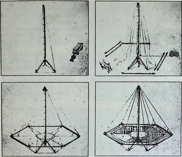
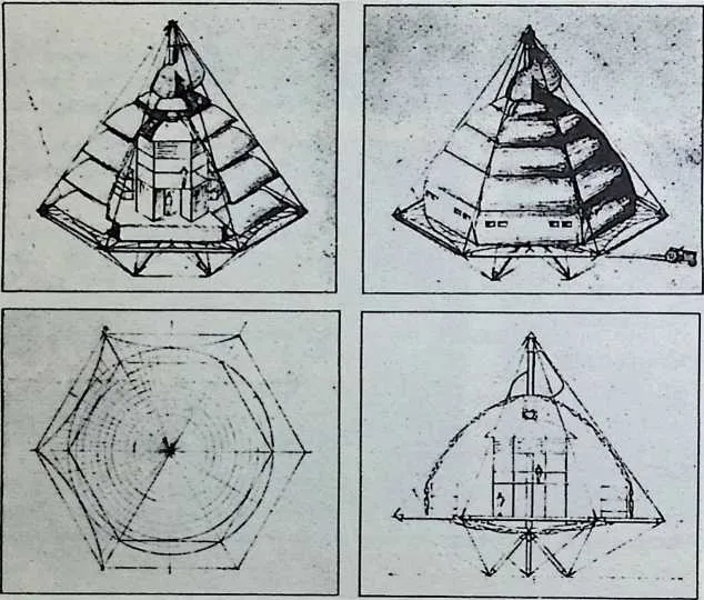 63-64 Sketches showing the construction of the Dymaxion Mobile
Dormitory around its central mast. (1931) Dormitory was a single-deck, wire-wheel
structure with airfoil-type hinged skin units. Presenting these drawings in his Shelter
magazine, Fuller suggested to the Russians that this structure would be of high
advantage to them in their cooperative farm operations; it would make possible the
migration of their farm workers with the seasonal patterning. The Russians
informed him that the application of science and industry directly to the
improvement of living standards was strictly non-priority; and that his devices
would breed popular discontent with the Five Year Plan strategies which, for almost
a generation, would require the reinvestment of all tooled productive capacities in
the further production of machine tools. The Soviet leaders maintained, however,
that after the primary Russian programs had been completed, this position
would be modified; greater emphasis would then be placed on consumer
goods.
89Fuller believes that this time may now be at hand. When Nikita S. Khrushchev visited the site of the American exhibit at the Moscow Fair, in May, 1959, and had his first glimpse of a Fuller geodesic dome, it was reported by the New York Times that, ”he could not resist turning back again and again to look at the huge dome made of pressed aluminum plates.’’ Said Khrushchev: ”I am thinking of authorizing Kucherenko (Vladimir A. Kucherenko, chairman of the State Committee on Building and Architecture) to do the same thing here in the Soviet Union.”
9065 Fuller has always had a catalytic effect on students.
91The drawings of the Dymaxion gas station shown here won the Architectural League of New York award for architectural student Simon Breines, in 1929. (Throughout the previous summer, the 4D house had been shown in the Architectural League’s New York quarters.) On graduation, Breines, using Fuller’s tensional-structure strategy, won second prize in the world architectural competition for designs for Russia’s Palace of the Soviets. (The first prize was won by another American, for a classical style building.) Breines’ solution was a large wire wheel in horizontal position. The Chicago World’s Fair of 1933 Transportation Building employed the principle for the first time. Its designer, Lombiere, of Paris Beaux Arts school, consulted with Fuller on its tensional structure, but clothed it in a classically styled cylinder. The Chicago World’s Fair °f 1933 also saw many features of Fuller’s Dymaxion house principles incorporated in its ”House of Tomorrow” exhibit. Although the House of Tomorrow looked as if it were hung from a mast, it was framed from the ground up in a conventional but hidden manner. The largest building constructed on the unit wire wheel principle was the United States Pavilion at Brussels World’s Fair of 1958, designed by Edward
9293Stone.
DYMAXION BATHROOM
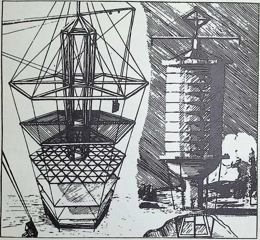
9566 Unitary bathroom shown as it would be hoisted aloft in 1927 multi-deck building. (This picture is also shown as 17.)
96mli
97 W2US2
98 UNITED STATES PATENT OFFICE
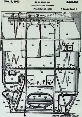
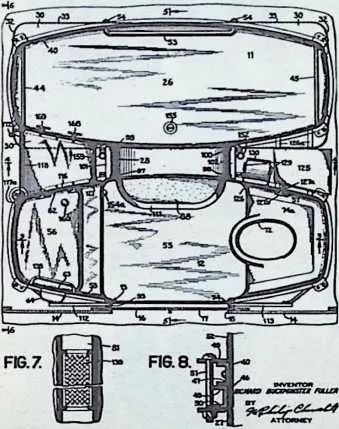
99 67–74 Patent drawings showing details of the Dymaxion bathroom. (1937)
100 95
101 FIG. 2.

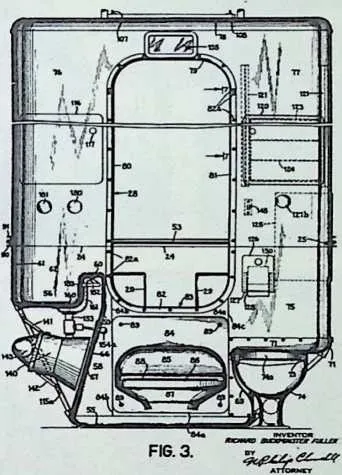
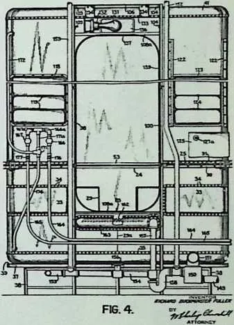
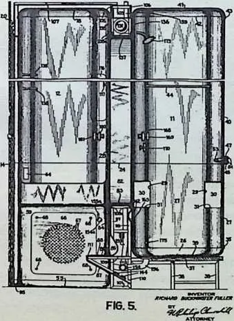
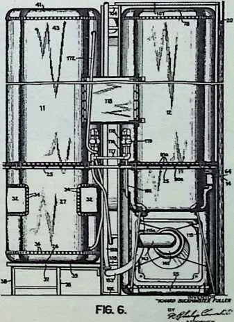
10475 The first Phelps-Dodge Dymaxion bathroom. Fuller improved on this model by making the front and back ”rooms” of the bathroom in identical oval pattern, thus enormously reducing tooling costs. (1937)
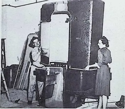
10576-79 Assembling the four main components of the Dymaxion bathroom. Each part was light enough and small enough to be carried through small doorways and up old-fashioned back stairways.
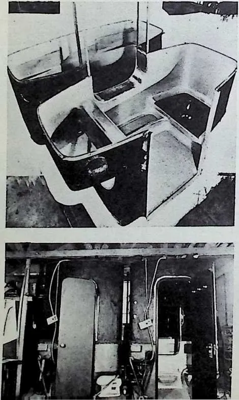
10780 Two completed Dymaxion bathrooms, showing electrical harnesses, and final control switchplate; together with air conditioning components. Each bathroom covered a floor area of 5 feet by 5 feet. In several instances two bathrooms were installed side by side as ‘‘husband and wife” units in guest and master bedrooms. (1938)
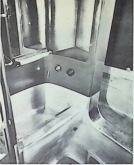
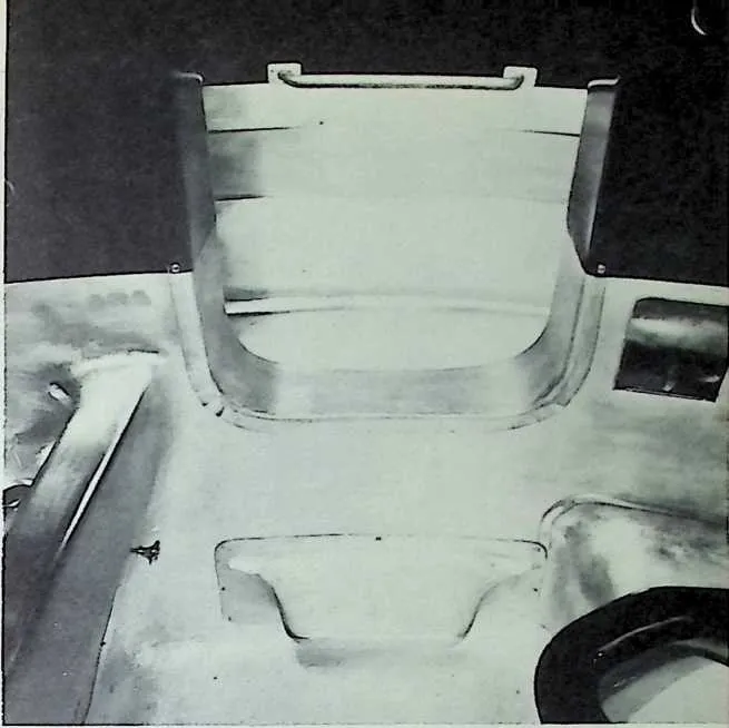
10982 Looking into the bathroom from the front door. Note the step for entering the bathtub and shower, at the same level as the bathtub bottom. Handles on either side of door, at entrance to tub and shower area, prevented the possibility of occupant’s falling while entering or leaving tub.
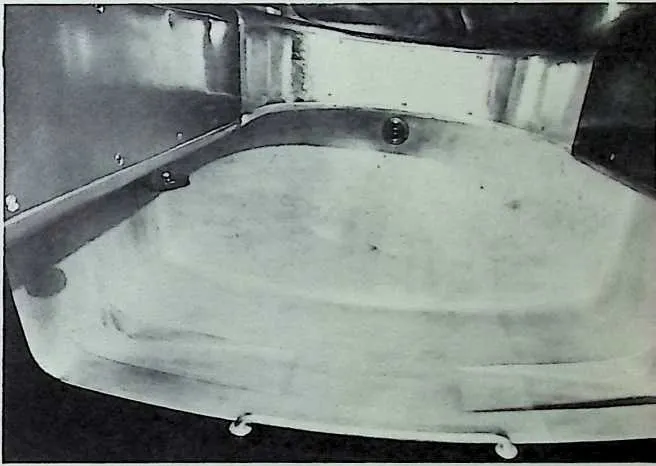
11084 View looking down into tub section. The tub was 27 inches wide, 3 inches wider than standard tubs, and permitted the occupant’s body to float freely. By placing the drain at center of the tub, Fuller was able to make the pitch of the tub floor so slight as. to offset the user’s tendency to slip. In addition, the tub surface was hammered to prevent slipping. Note the alcoves for sponge, soap, and arm rest at the comers of the tub;-the plastic tub and shower handle on interior, at the. right of the doorway; and the seat saddle at the foot of the doorway.
11181 View inside bathroom, showing cupboard opened in such a manner that mirror is in use even when door is open. A light was installed along base of mirror. The cabinet provided space for items as large as 5 gallon buckets. Round water control handles were of red and blue plastic. Hot and cold color-coded water handles are now in use on bathroom fixtures in many parts of the world. Note the circular air exhaust grill on lower face of the wall, below the washstand through which steam and stale air were evacuated. The washbasin was without knobs or spigots. The waste handle for the washbasin was a black knob at knee height on the outside of the basin. The drain was actuated by a knob pushed to the right with knee.
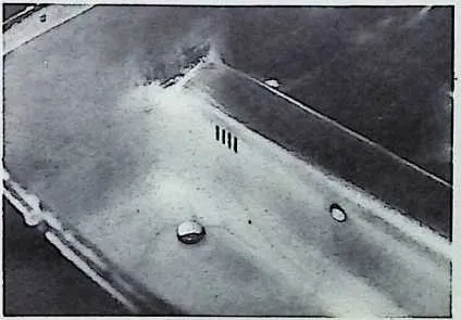
11283 View of interior of the knobless basin, showing the orifice, at lower right center, through which hot and cold, control-mixed water, spurted into the washbasin from the front toward the back of the basin. This direction of the water jet prevented water from going up the cuffs, and back-splashing. Note the overflow exhaust slots to prevent back-syphoning.
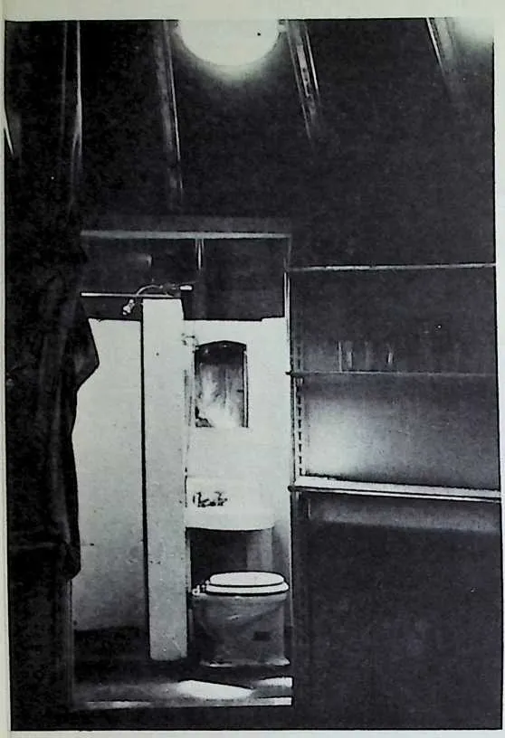
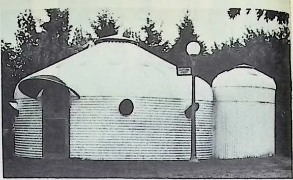
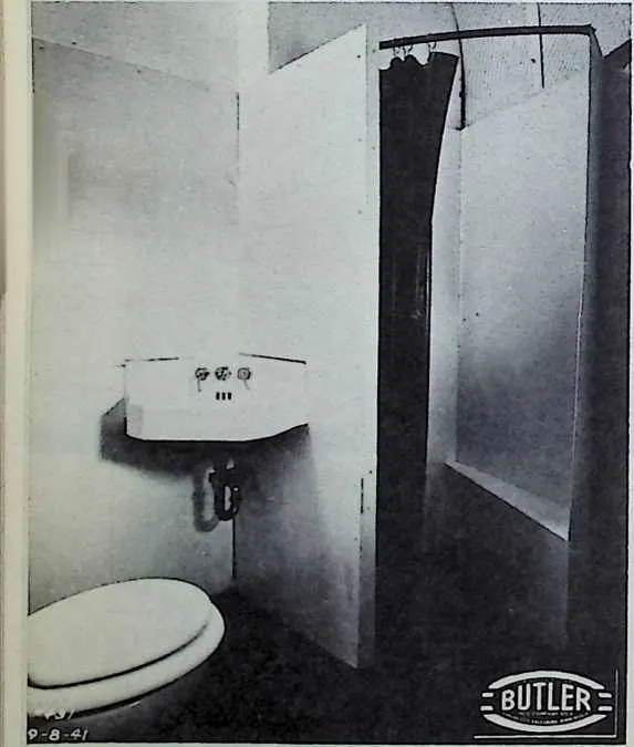
11485-86 Inside and outside of Fuller’s cylindrical bathroom designed for Butler Manufacturing Company in 1940. The ground-level area, as shown in the interidr view, contained the shower bath, basin, and toilet seat. The water tank was above the ceiling, in the cylinder’s head. The cylinder was 4 feet in diameter. The exterior view shows the bathroom attached to Fuller’s 1940 Deployment Unit. The septic tanks were contained in the cylinder base below ground level.
11587 Another version of Fuller’s Dy maxion Deployment Unit manufactured by the Butler Manufacturing Company, in Kansas City. The seat, basin, and shower, with their flooring and walls, were mounted on a box chassis along with the kitchen plumbing equipment. The latter was placed on the other face of the central wall within which plumbing manifolds, electrical harnesses were installed behind readily demountable panels. (1941)
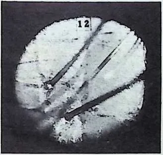
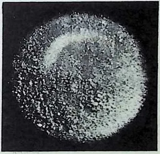
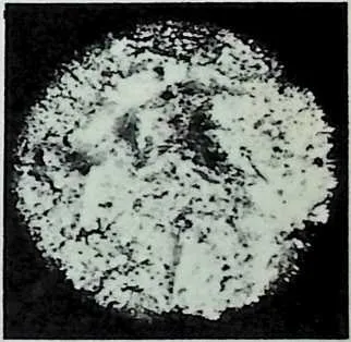
11788-91 Fuller considered the Dymaxion bathroom as an interim, mass-producible, sanitary facility; his fog gun, pictured here, afforded a new method of bathing. It combined compressed air and atomized water with triggered-in solvents. The kinetic force of the high-pressure air stream was utilized without the skin-damaging effect unavoidable in high-pressure needle-pointing of water streams. Generalizing from his Navy experience, in which engine room greases on the skin were almost unnoticeably removed by wind and fog on deck, Fuller reasoned—and later demonstrated—that the feeding of atomized water and air at high pressure on to the skin surface would accelerate the surface oxidation, and release the surface cells themselves, along with the attached dirt.
118The round pictures show magnifications of the skin surface. Two of the pictures show the dirt interspersing the ”coral reeflike” structure of the pores. (1927–1948)
119 1OO
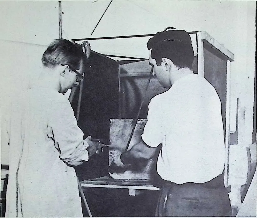
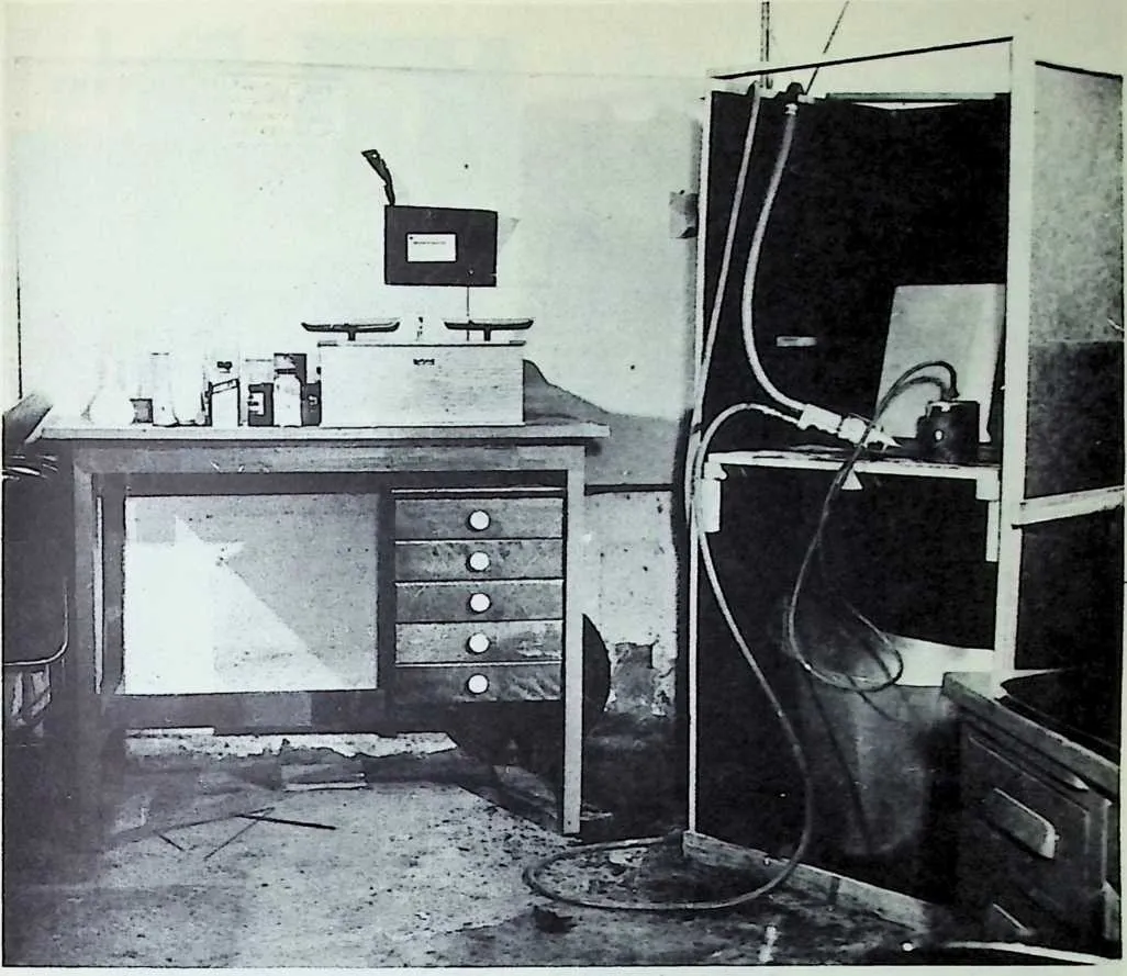
12112292 Research students at the Institute of Design, Chicago, in 1948 testing the Fog Gun. (Subsequent experiments were conducted at Yale and other universities.) A one-hour massaging pressure bath used only a pint of water. If fog gun bathing were done in front of a heat lamp, all the sanitary and muscle-relaxing effects of other types of bathing could be effected without the use of any bathroom. Since there were no run-off waters, tons of plumbing and enclosing walls could be eliminated, and bathing would become as much an ‘‘in-the-bedroom’’ process as dressing. Fuller holds that the other functions of the bathroom may be effected by odorless, dry-packaging machinery, employing modern plastics, electronic sealing, dry-conveying systems.
123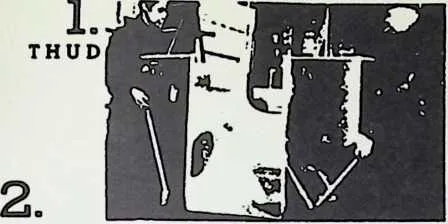 THE NEWEST
prefabricated bathroom
IS ALSO NEAREST
124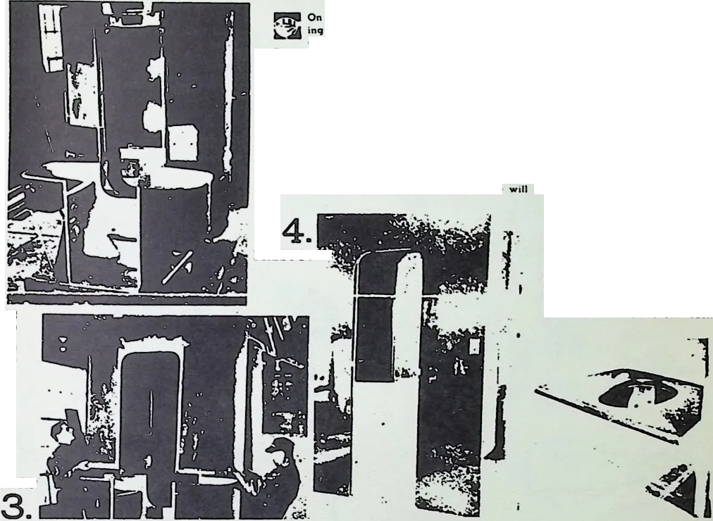 the 29th floor of 40 Wall Si. there sits the finished model of a new plumb fixture that
might well bug the eyes of any by-standing master plumber, a fixture that to all intents and
purposes constitutes a one piece bathroom. Designed by Architect Buckminster Fuller Dymaxion
House. Dymaxion Carl it accomplishes by the simple connection of four basic parts, a complete
bathroom weighing 404 pounds, with integral lavatory, toilet and bath, first known as the five by
five (because that’s the space it takes up*, the official designation is now ’The Integrated
Bath’.
125 PRESTO!
126 U
127 SNAP
128 O
129 In the research department of the Phelps Dodge Corporation it sits, ready for moderate production (100 units) in 1937. Architect fuller has assigned his patents to the PD organization, and rumor discerns a new manufacturing and marketing subsidiary in the immediate oiling. The range of uses for the unit is broad: pullmans. planes, trailers, trains, but mainly small homes. In fact. Mr. fuller hopes this light compact, complete bathroom will even inspire renters to install copies in their apartments and remove them when they move, lation for the immediate future the device
130 All of which lies in the realm of spreu probably induce fewer orders lhan conversations. None the loss the fact remains that this prefabricated bathroom comes closer to commercial reality than any of its predecessors.
131 The Integrated Bathroom consists roughly of two oblong sec lions that form a partition where they join, which conceals the piping and other mechanical appurtenances. The sections (each a monomelal stamping) arc each split in the middle, the (op being aluminum and the bottom 272 pounds of sheet copper unmetallized and tinted by a coating of silver, tin and antimony alloy. Tho bottom of one section is the lavatory and toilet, of the other a flat-bottomed tub.
132 The toilet, though reminiscent of the old backyard one-holer is fully sanitary. The seat lifts and remains upright by compression against the walls. Underneath is a standard form of bowl (though chrome nickel bowls are also available).
133 Two men can handle an installation in three hours, for all piping except a minimum amount of connection material is integral with tho unit. So are electric connections, ventilation equipment, etc. fresh air is drawn by a motor under the lavatory from the nearest room, and exhausted—wherever circumstances permit.
134 Miscellaneous features: A composition Venetian blind gives privacy to the bather* and. while permitting the escape of steam, prevents the escape of water. The door frame between the two sections is six inches thick, permitting use as scat. Complete cleansing of tub is easily attained. The plumbing layout was devised in collaboration with a local master plumber, copper tubing being used lor water lines. Particular care wax used to avoid back-siphonage possibilities. Sliding doors conserve space. The metallic finish has a ‘‘hammered’’ appearance while at the same lime being thoroughly sanitary, the inventor claims. Under sur* faces of the base metal are covered with Dum dum. a sound deadening material. An electric heating system between .the two units warms the metal itself, radiating heal to occupant of bath room. Removable panels permit access to plumbing traps and connections under toilet and lavatory.
13593 Reproduction of a page from The Ladle, April, 1937, official publication of the New York State Association of Master Plumbers. The article documents the.jnaster plumbers’ enthusiasm for Fuller’s 1936 Phelps-Dodge version of his mass-reproducible unitary bathroom as a chattel mortgage appliance. Despite the plumbers’ enthusiasm and large public demand, industry failed to venture in the bathroom’s production and distribution.
DYMAXION TRANSPORT
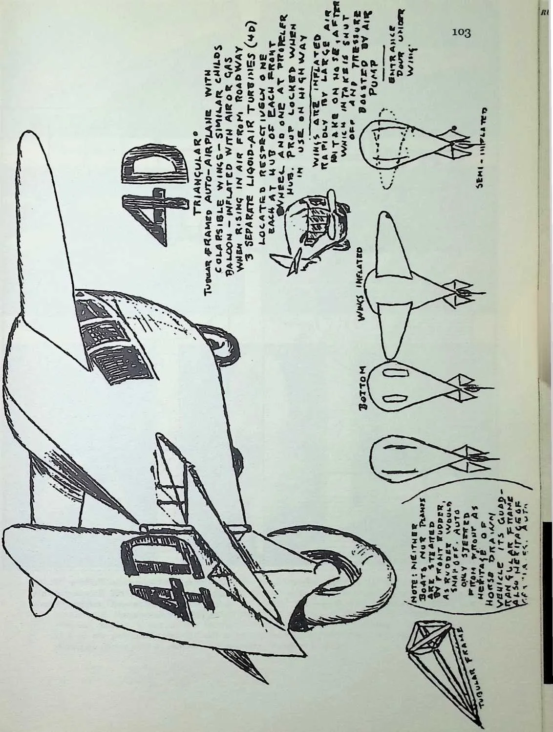
13694 Early 4D version(1927) of Fuller’s Omni-directional Transport.
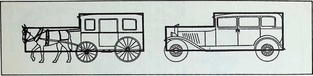
138 95 The standard J9J2 automobile sedan body presented almost the same contour as
139 the unit composed of a horse and closed wagon.
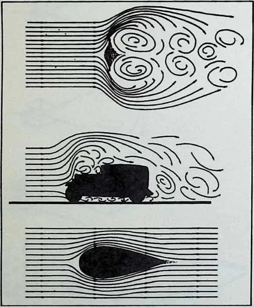
14196 Fuller’s early study of air flow effects around a conventional car and one whose contour was an ideal streamline form (1930).
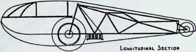
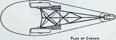
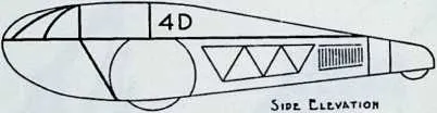
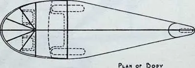
14297 Study, published in Fuller’s Shelter magazine, in 1932, of the framing, seating arrangement, traction and steering systems of the 4D Dymaxion car.
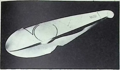
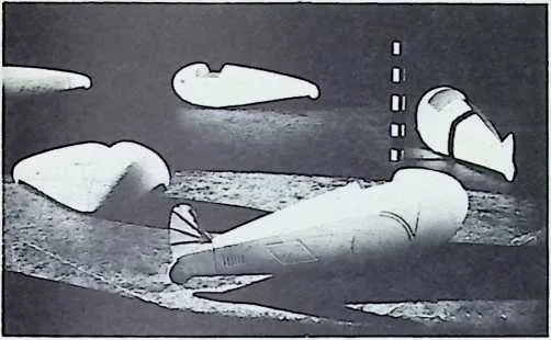
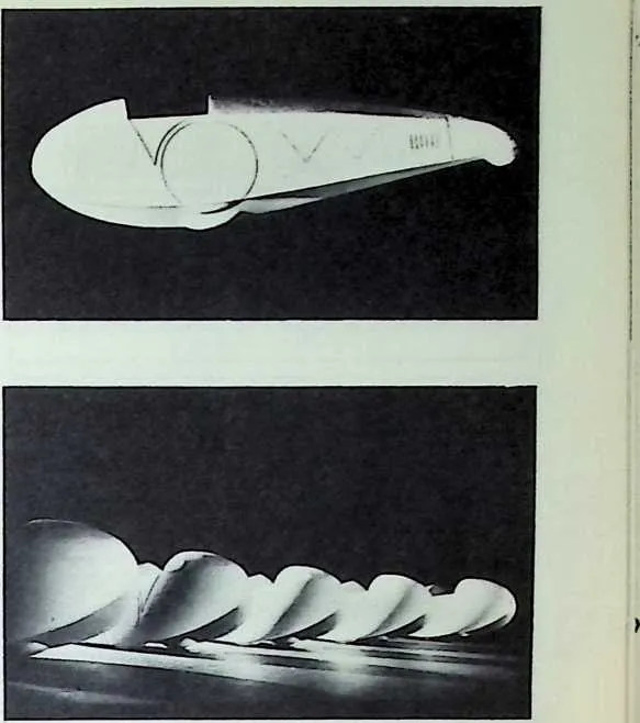

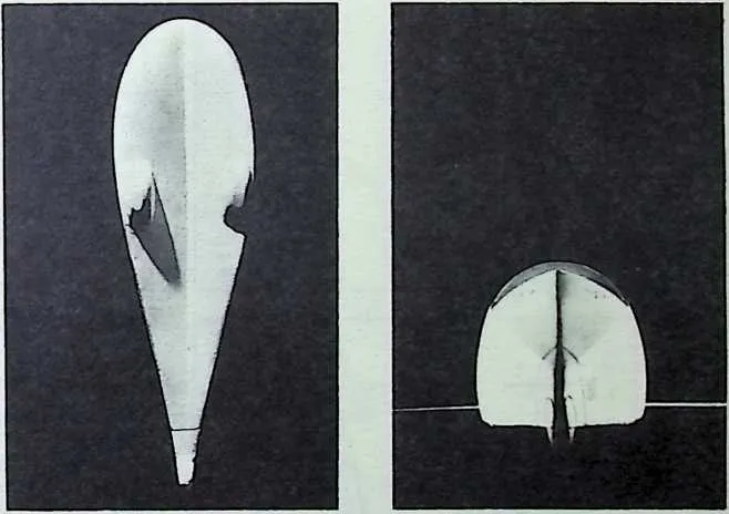
14498-104 Studies of the hull structure of the 4D Dymaxion car. The hull was to have an inverted V bottom to provide air keel at high speeds as well as to lift the tail of the transport. The consequence was to be an infinite wheel base. The faster such a car accelerated, the smoother would be its ride as in the case of the airplane. There was planned, further, a fan tail for increased rudder windage, when ”planing.’’ Under the skin of the projected transport was a pneumatic, longitudinal, guard rail. (102 is also shown on facing page of chapter on Dymaxion Transport Units.)
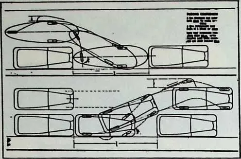
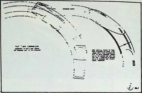
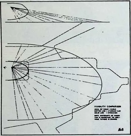
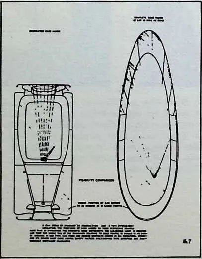
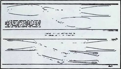
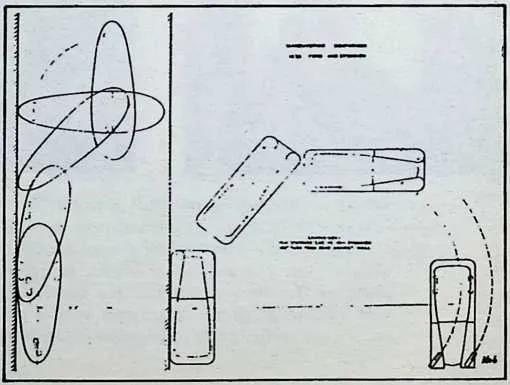
147 109 Rear vision comparison: the 1933 standard sedan and the Dymaxion.
- 105.
- Sketch showing parking path of the Dymaxion car compared with that of a standard 15-foot car. A 15-foot Ford sedan of 1932 required 21 ¥2 feet of parking space. The 19-foot Dymaxion parked in a 20-foot length.
- 106.
- Sketch showing the turn path contours of the Dymaxion and the standard 1932 car.
- 107.
- Front vision comparison: the 1933 standard car and the Dymaxion.
- 108.
- Comparison of collision-avoiding capabilities: the Dymaxion and the I5-foot standard car.
- 110.
- Maneuvering comparison: the 1933 Ford and the Dymaxion.
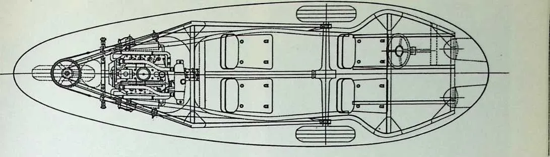
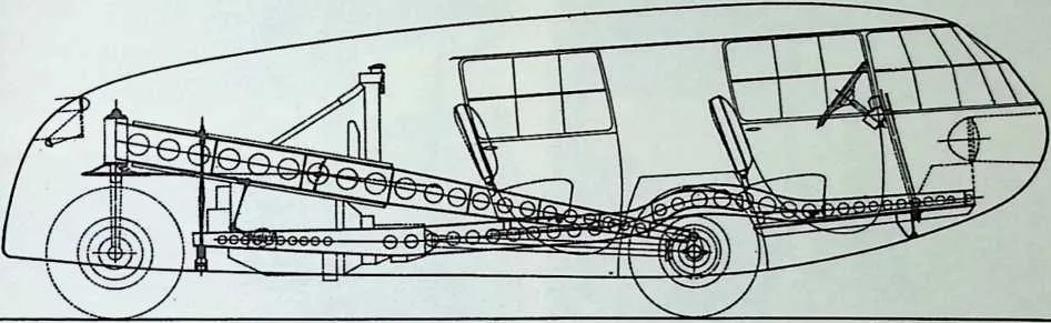

150Ill Scale drawings of the Dymaxion car No. I.
- 112.
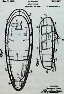
- The first page of the Dymaxion car patent.
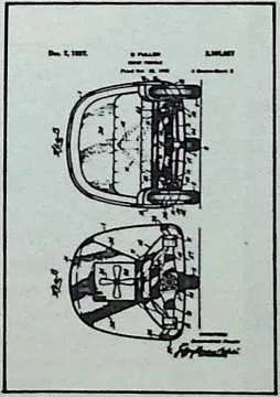
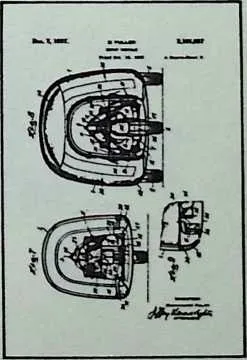
151113-115 Patent drawings showing the front, rear, side views, and main structural details of the Dymaxion car below.
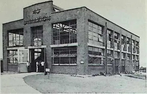
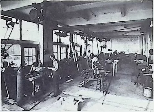
154116 The Dynamometer building of the Locomobile plant in Bridgeport, Connecticut, which was taken over by Fuller for development of the prototype Dymaxion cars. (March, 1933)
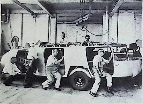
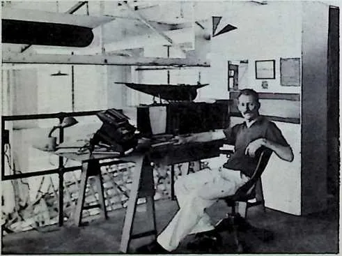
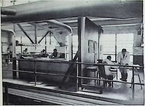
156117–119 Interior views of the Bridgeport plant building during development of the Dymaxion cars’ prototypes.
- 120.
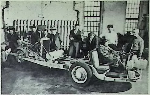
- Starling Burgess, chief engineer in the Dymaxion car project. A famous naval architect, he had previously designed two successful America’s cup defenders, and had also invented and flown the first successful Delta wing airplane, the Burgess-Dunn plane. During this period, Burgess was ‘‘between cup defenders,’’ and Fuller persuaded him to serve as assistant in experiments to test ‘‘the ground taxiing qualities of the 4D omni-directional transport.’’ Fuller shared with Burgess a conviction that ‘‘inventorpioneers have a responsibility to society requiring that they render their publicly exposed inventions in so competent a manner as to provide means of judging the relative merits of the invention unembarrassed by shoddy, makeshift irrelevancies.” (1912–14)
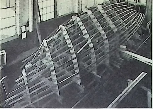
- 121.
- To obtain Burgess’ services Fuller had to take on the building of a Bermuda class cruising-racing sloop which Burgess was committed to produce. The boat-building program fitted in neatly with the scheduling for the Dymaxion.
- 122.
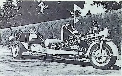
- Starling Burgess seated at the wheel of first Dymaxion car, before the chassis was road tested. Fuller stands at the right. (1933)
- 123.
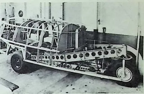
- Chassis of car No. I made of chrome-molybdenum aircraft steel. Notice the aircraft-type dished lightening holes in the frame members, and the forged steel rudder post, leading from the A-frame bearing to wheel hub. This structure permitted full-circle rotation of the steering wheel. Conventional steering wheels are limited to 34 degrees of steering angle.
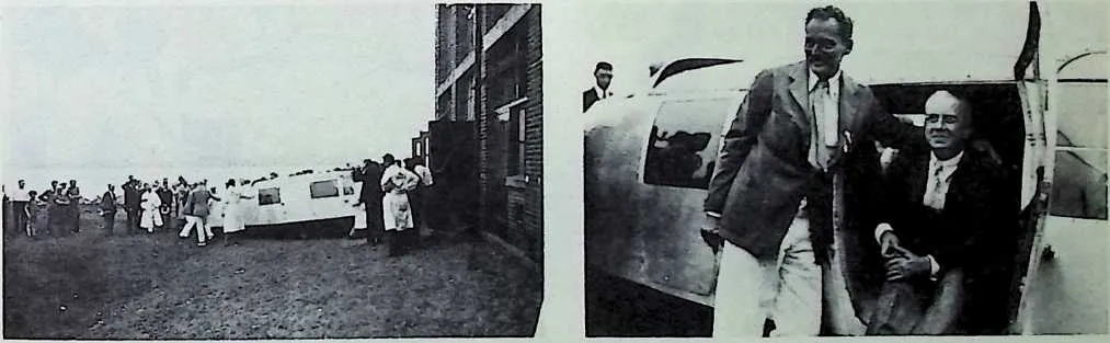
160 124 Body construction of Car No. 1.
161125 The first completed Dymaxion car rolled out of the Bridgeport factory on July 12,1933—Fuller’s thirty-eighth birthday.
162126 Fuller and Starling Burgess with car No. I.
164 no
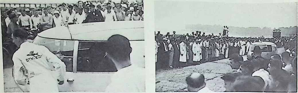
165127–128 At Bridgeport, crowds lined the private speedway of the leased Locomobile plant, to watch the first Dymaxion road tests. Extending through the roof above the driver’s seat is the car’s rear view periscope.
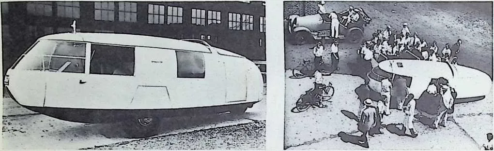
167 129 Side view of Car No. I.
- 130.
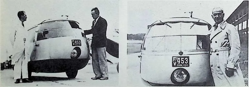
- The lines of the Dymaxion are modern, even by present day standards. Here the Dymaxion is shown next to a contemporary Franklin. Mexican artist Diego Rivera is shown standing between car doors, far side of car, coat under arm.
- 131.
- Flyer ”Al” Williams (right) and Starling Burgess with Car No. I. Williams later bought this car.
- 132.
- Ralph de Palma, famous racing driver, standing beside Dymaxion. De Palma brought the first Fiat to America before World War I and participated in early Indianapolis races.
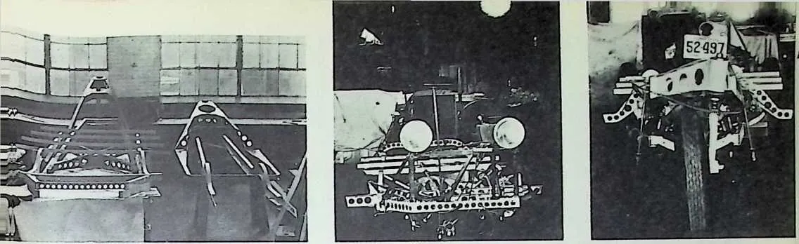
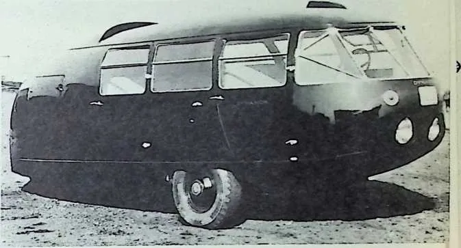
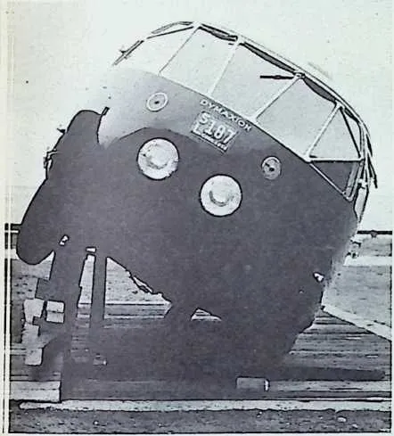

171136 Testing the wheels of car No. 2 for strength and load distribution.
- 133.
- Comparison of relatively heavy two-frame structure of the Dymaxion car No. I (right) with the delicate three-frame structure introduced (left) in car No. 2.
172134–135 Construction details, car No. 2.
173137 Car No. 2, complete. Headlights are recessed in body, providing ”nostrils,” which were intakes for air. Dry ice cooled the incoming air. (1934)
174TEX CEXTX A a>r\
175Ute Saturday Review
176 of Literature
177138 H. G. Wells, on a visit to America, in 1934, was photographed in front of the Dymaxion car. The Saturday Review of Literature published this picture on the front page, to illustrate a review by Elmer Davis of Well’s latest book. Caption: ‘‘The Shape of Things to Come Confronts Mr. Wells.’’
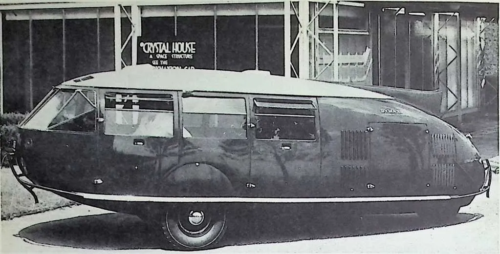
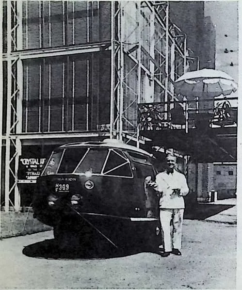
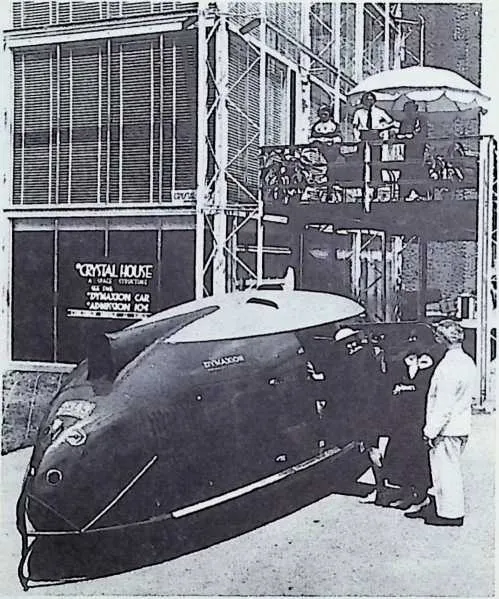
179139-141 Fuller’s Dymaxion Car No. I had been in a collision in which the driver had been killed. The accident took place in front of the Chicago World’s Fair in 1933. The other car, driven by a prominent politician, was removed from the scene before the newspaper reporters arrived on the scene. Front page headlines of Chicago, New York, and world papers carried variations of the statement: ”Freak car rolls over—killing famous driver—injuring distinguished international passengers.’’ Although the coronals inquest 30 days later exonerated the Dymaxion car, there was no recantation of the earlier damaging news. Because Fuller was convinced that the principles of his transport were sound, and embodied technical gains over previous transport, he considered it ”his responsibility to obliterate the unwarranted stigma.’’ In 1934 he completed and sent to the Chicago World’s Fair his car No. 3, pictured here. This cost him his entire family inheritance. The Chicago Fair featured it as the last episode in their pageant of American transportation, ‘‘The Wings of a Century.”

181Ill 1|i #|l
- 142.
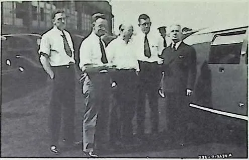
- Fuller with engineers of the Goodyear Corporation, at what was the zeppelin mooring field, at Akron, Ohio. The Goodyear company supplied tires for the Dy maxion on its way to the Chicago World’s Fair of 1934. Bald-headed man in center is Dr. Arnstein, then chief engineer of the Goodyear Zeppelin Corporation, and for the succeeding 18 years vice-president and director of research of the Goodyear Corporation. Dr. Arnstein, possibly the world’s greatest living structural mathematician and originator of the isotropic vector matrix calculus, has been for a third of a century an enthusiastic supporter of Fuller’s work. His mathematics is related to Fuller’s Energetic-Synergetic geometry.
- 143.
- Leopold Stokowski and his wife bought the Dymaxion Car No. 3 and sold it a few months later. During the nex( nine years the car was resold many times, and for a long span disappeared from sight. It was rediscoved, finally, in Brooklyn, in 1944,’and repurchased for Fuller by his friend, J. Arch Butts, Jr., of Wichita, Kansas.
- 144.
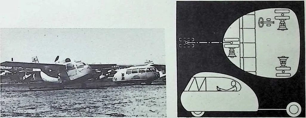
- Car No. 3, which was estimated to have been driven some 300,000 miles, was restored by Fuller to prime condition. It is shown here at the Wichita, Kansas, airport, in 1945, standing next to the Republic Seabee amphibian plane, which at that time Fuller owned and piloted.
- 145.
- Fuller’s original caption read:
183With the one-half-pound-per-horse-power gas turbine coming of age, the trend is to reexplore promptly the possibilities of earth-bound vehicles. Pictured is the Dymaxion No. 4, featuring coupled-steering of all three ‘‘duo-tired” wheel assemblies. Each wheel assembly contains its own gas turbine. The fuselage is suspended by three aircraft type vertical aerol struts, and has a retractable rear wheel tail boom for lengthening wheel base at speed. It is 7 feet wide and 10 feet long (contracted) with cross-wind ‘‘fairing.” It has a 7-foot driving divan, convertible into a large bed. It may ”revolve into” half the parking length of present cars. The top is a convertible aluminum watermelon type. It has a faired belly with high clearance for field work, will ‘‘gun” high speed turns without skid. Weight 960 lbs.
MECHANICAL WING
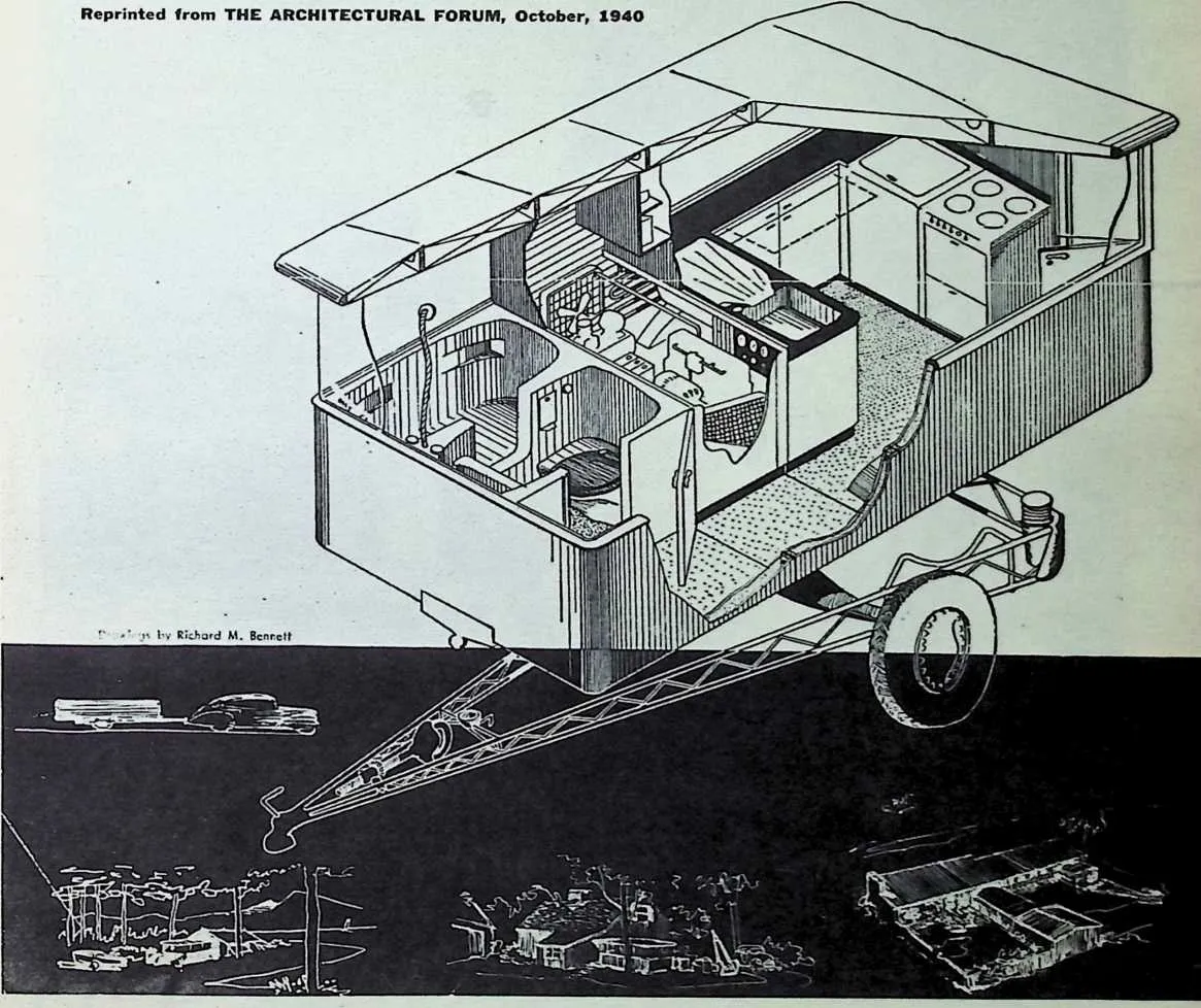
184146 In 1940, Fuller designed the Mechanical Wing, a compact package intended to provide the mechanical essentials of contemporary American life in a form sufficiently mobile to be transported on an A-frame to any campsite, barn, or shell. The unit was attached to a tubular A-frame trailer, and was equipped with integral jacks mounted on castors.
185The Mechanical Wing consisted essentially of (1) a Dymaxion bathroom, with hermetically-sealed waste packaging and chemical disposal apparatus; (2) an energy unit’, containing diesel engine, air compressor, electrical generator, and hot water heater; (3) a kitchen and laundry unit, with sink, laundry tub, electric range, refrigerator, and storage space for dishes and silver. The Fuller A-frame afterwards became popular as a trailer frame for transporting boats
187CHEATED HY Hl CKMIXSTEH Fl EEEH Kill THE .
188k
189 Burn 1695, Milton, Muss. Inventor machines, building products, Dymaxion house, Dymaxion car, one-piece prefabricated bathroom. Outstanding exponent of industrialization of building. Author ‘‘Nine Chains to tho Moon.’’ At I-resent technical consultant to ‘‘fortune.’’
190 THE MECHANICAL WING a compact. mob Jo package in which the mechanical essentials of contemporary U. S. living can be transported to tho Vermont farmhouse, lakeside camp site, week-end or vacation house, or incorporated in a permanent dwelling.
191 Il is attached to a tubular steel A-frame trailer, frame integral with axle. Attaches to car by ball joint hitch, weight sprung by car. Has integral jacks on casters for maneuvering by hand, blocking up Wing, etc. A-frame alono Is useful as luggage, fuel, boat and water carrier, also as a crane for manipulating heavy objects. Note hinged-up tubular barrel chock.
192 Bath-dressing room unit supplied optionally with (1) waler lino connection whore running water available, (2) combination comprossed-air, water
193 J SFMIIEH Ok THE AHCIIITECTL HAE HlHI
194 and chemical fog gun cleansing devices, (3) hermetically scaled waste packaging and chemical disposal apparatus.
195 Tho energy unit is located between bath and kitchen-Contains diesel engine (lip. optional), ecctrlca generator, air compressor and tank, battery and radiator. Tho last uses domestic hot water to warm incoming air. The fan shown can be reversed in summer to exhaust warm air from living units.
196 Kitchen and laundry unit, with sink, laundry tub. electric range and refrigerator, storage space tor dishes, silver and linen. Dry warm storage shelves over diesel above sink.
197 Side walls: waterproof, synthetic-resin-glued plywood truss. Walls and floors of the threo units
198{Continued on page 92)
200116
DYMAXION DEPLOYMENT UNIT
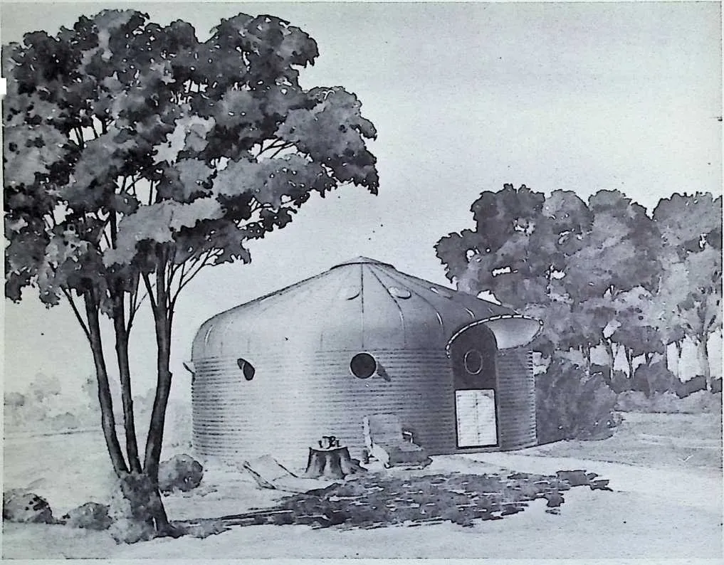
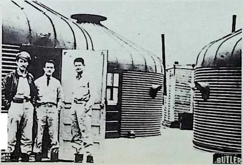
202147 Converted grain bin, re-designed by Fuller as the Dy maxion Deployment Unit. (1940–41) The unit was scratched from the British wartime acquisitions program when it was discovered that all the steel that the British could ferry across the Atlantic from the United States would be needed for weapons, or other logistics higher in priority than dwelling functions. The Butler manufactured Dy maxion Deployment Unit was considered for major housing use in the United States, but again was sidetracked because of the priority of weapons steel. Almost abandoned, the Deployment Unit was suddenly accorded high priority for use on the Persian Gulf, as radar shacks and desert dormitories for American and Russian mechanics assigned to assemble, transfer, and fly-away delivery to Russia of United States fighter planes.
203Mm* 7,1M4. a a ruuxx
204 aaruun IW*
205 MxkT, 1M4.
206 M4 T. IM* a. a naxaa DOJM
207 kl~d 7. 1*44. a a rvu XM3.7M
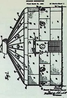
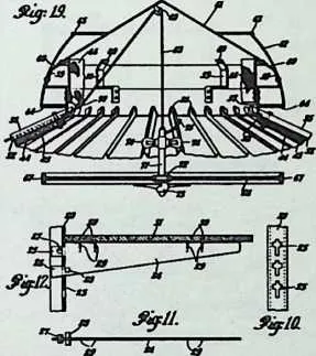
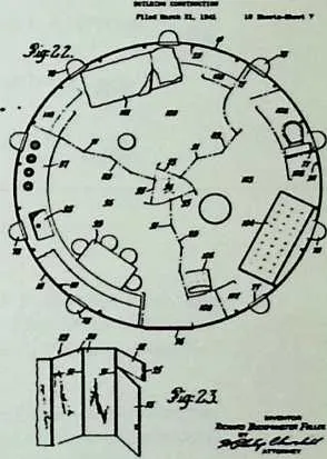
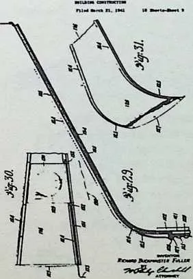
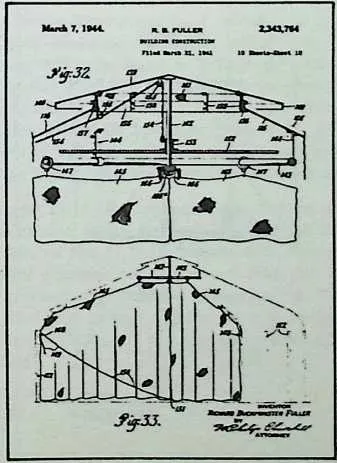
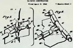
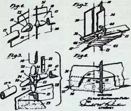
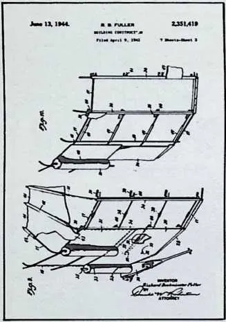
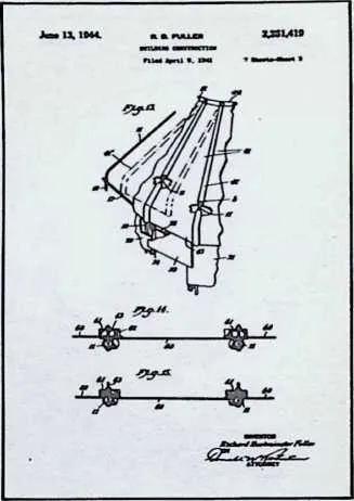
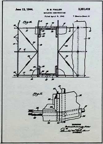
208 148–154 Initial pages from Fuller’s patent covering prefabricated buildings, showing construction principles of the Deployment Unit.



210 J 13. 1M4. a rwxca 2JSMI*


213JU3XOO
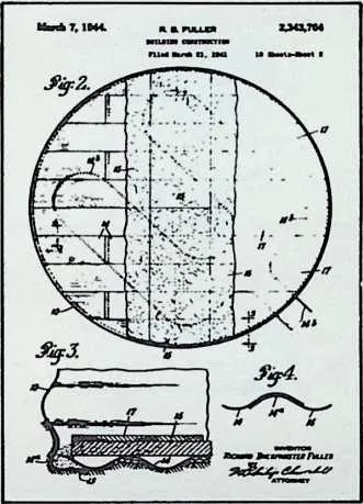
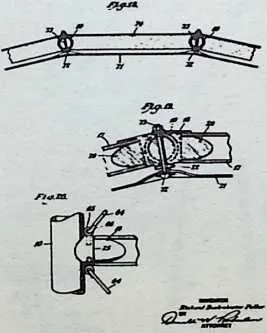
214155–160 Initial pages from Fuller’s patent covering the fabrication of structures suitable for small houses; shows the construction principles of the Deployment Unit.
215 PLANNING PRINCIPLES THAT INSURE HEALTHFUL LIVING ENVIRONMENT
216LIVING CONDITIONS FOR DEFENSE WORKERS THAT ADD TO HUMAN EFFICIENCY
217CIRCULAR SHAM PROVIDES1
- MAXIMUM FLOOR AREA MA UNIT OF WALL LENGTH
- MAXIMUM CUBAGE WITH IEA5T MATERIAL
- ATMOSPHERIC CONTROL IT THERMODYNAMIC ANO AIRO-DYNAMIC TECHNIQUES
218SPECIFICATION:
- STRUCTURE-INTEGRAL WITH COVER SECTIONS
- FINISH: SHOP RAXED EINC OXIDE ON GALVANHED STEEL
- WEIGHT: JtOO POUNDS COMPLETE
GROUP UNIT

- 161.
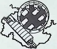
- Planning sheet, indicating design of D.D.U.
- 162.
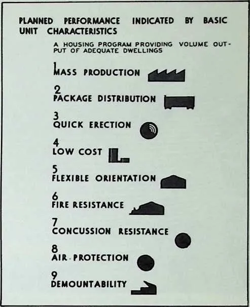
- Sheet listing the design responsibilities of the D.D.U. In all Fuller projects, the design responsibility goes beyond the static, physical end product. The ‘‘comprehensive design responsibility” is concerned with what Fuller calls the product’s ‘‘cradle-to-grave’’ life:
220‘‘. . . its internal and external relationships, the complementarity of the environmental control in respect to total world pattern trending, and the advantages of individuals with respect to that trending, world-around resource priorities, logical manufacturing and distributing networks, the most economic production means, the designed use of the most effective tool complexes, production flows, distributing compaction, and safeguarding of transported parts, designed transport most suitable to local and world delivery of environment controls, designed erection strategies suitable to terrains and climatic conditions, designed ease of assembly by human beings of any language or background, designed inclusion in distributed package of all tools necessary for field erection—including hand tools, scaffolds, masts, booms, and sub-assembly jigs, designed operability of structure and its mechanics, designed periodic frequency of anticipated maintenance, servicing, and parts replacement; designed removability without parts damage; designed retransportability and storage ability for further installations or upgrading rebuilds.’’
221Tool kits were included in the D.D.U. packages. Each contain the tools typically used by carpenters, auto mechanics and householders. At the outset of World War II, Fuller insisted on including these kits in the D.D.U. shipments; Butler and government officials protested that this unheard-of practice would mean that the kits would be immediately pillaged by the men who erected the units. Fuller replied, ‘‘That’s just what I expect, too.’’ His assumption was that this pillage would be a very low cost bonus incentive to attract the installing workmen who would get the structures up in a hurry in order to be off with their booty. It worked.
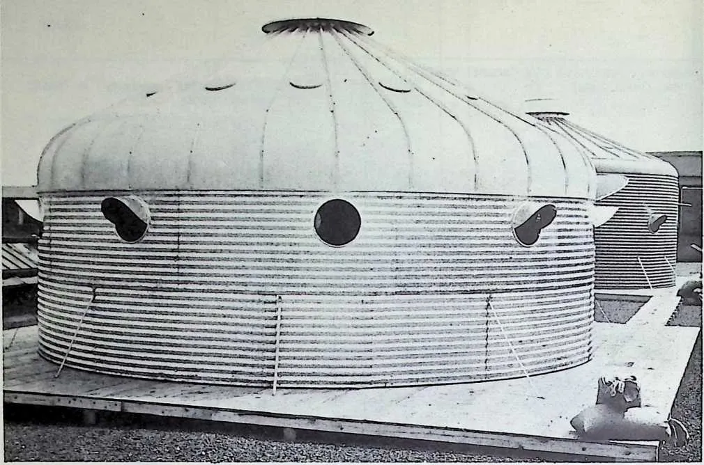
- 163.
- Small and large radius compound curvature eaves were used to convert Butler’s cone-topped grain bins into dwelling units. Fuller found that the compound curvature stiffened the entire structure, and that the larger the radius of the eave, the greater the strength. 1940
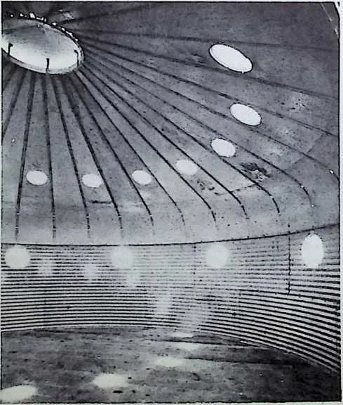
- 164.
- Interior view of the 20-foot-diameter D.D.U. conversion of Butler grain bin, with added portholes, skylight, and ventilator.
225121
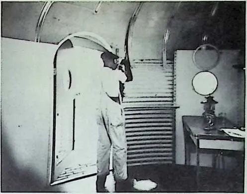
- 165.
- Fuller lined the converted grain bin with wallboards, on the inner surface of which fiberglass insulation had been laminated. The wallboards were held in place by vertical channels whose entire length was stamped with keyholes; the inner ends of the long bolts that held the grain bin body sheets together were used to fasten the keyhole channels. The keyholes were later used for brackets on which shelves and any type of appliance could be mounted. The ceiling of the structure was lined with 3-inch thick fiberglass bats enclosed in fabric, providing extraordinary insulation and sound absorption.
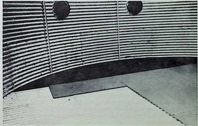
- 166.
- Fuller invented a demountable, dry floor assembly to be laid directly on leveled earth, within a brick circle whose diameter was 1 foot greater than that of the D.D.U. (1941). A galvanized wire strap, encircling the brick ring, pulled the ring together much as a barrel strap pulls together the barrel staves. On top of the leveled earth (within the brick ring), Fuller laid corrugated, galvanized steel sheets, over-lapped sidewise and endwise as shown in lower left corner of picture. Above the corrugated ‘‘snowshoes” were Vi-inch felted insulating boards (Celotex), butted together, but with no fastenings. On top of the felted boards was tempered, hard-pressed Masonite, Vs inch thick. The Masonite pieces were placed with their main axis at 90 degrees to the Celotex pieces below in such a manner that the joints of the lower and upper layers never coincided. Because hard Masonite tends to curve outwardly along its shiny surface, Fuller turned the shiny surface upward, permitting gravity to flatten out the arch. The ends of the Masonite flooring pieces never curled upward. Thus the whole floor represented a flat assembly held together only by gravity and friction as a single disk sandwich whose top pieces were butted tightly together, yet could be lifted to allow vacuuming out of the edge cracks. Fuller has used this type of ‘‘unfastened’’ flooring on various terrains, and used it in South Africa in 1958. In recent years he has substituted unitary polyethylene sheets for the corrugated metal, finding that this makes an adequate moisture barrier.
228 /nuiiiiiiiiiu..
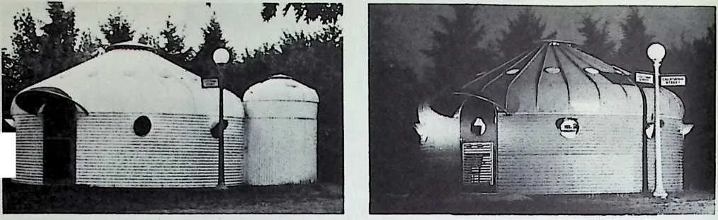
229 167 The D.D.U. shown here was installed in Haynes Point Park, Washington, D. C. in April, 1941, for study by government and military housing agencies.
230 At that time, the package price of the D.D.U., with the cylindrical bathroom, and the Montgomery Ward furnishings was $1250, including the kerosene ice-box and stove.
- 168.
- The round porthole windows were glazed with acrilic plastic. The D.D.U.’s were the first structures, other than airplanes, to use this World War II, high-priority material. The skylights were screened for protection from bomb debris.
- 169.
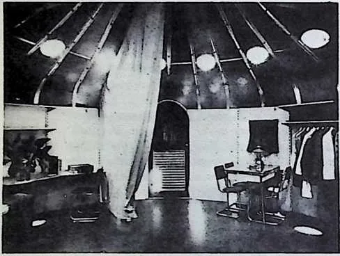
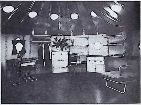
- The front door was designed for use both winter and summer. Note the lower screen ventilating section, on inner side of which is button-in window.
- 170.
- The smoothness of the dry-laid Masonite floor, and the tightness of its seams, made for both extreme resilience and cleanliness. Note the shelves and clothes hangers installed on keyhole channels. Note also the curtain at upper right, drawn up as in a theatre’s proscenium arch. Its bottom edge was weighted with tire chain so that when the curtain drawstring was released, the curtain shot into position like a grapefruit partition web, dividing the D.D.U. into pie-shaped segments. When these curtains reached common center, their edges were buttoned like Pullman-berth enclosures. The heavy tarpaulin curtaining material was fireproofed. Along with the sound absorption effect of the ceilings, it gave surprising privacy to the separated areas, in each of which were installed roll-away divan couches.
- 171.
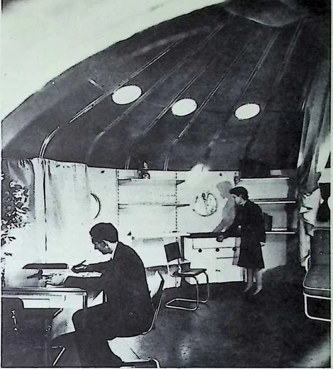
- Architect Walter Sanders, head of the Department of Architecture, University of Michigan, and his wife ‘‘test-dwelt’’ the D.D.U. in Washington, and found it completely satisfactory. (1941)
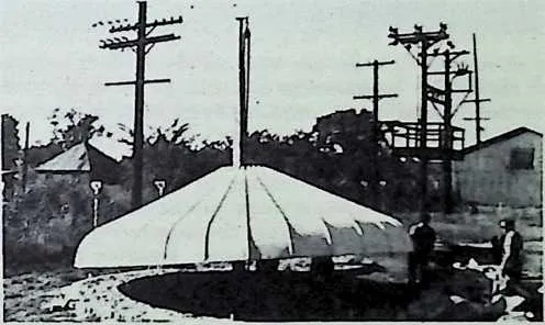
- 172.
- Similar to Fuller’s Dy maxion 4D house, the D.D.U. was always erected from the top down. The roof parts were assembled on the ground and hoisted aloft. The body sheets were installed at a comfortable working height for workmen standing on the ground, and were hoisted in consecutive tiers. Butler’s conic grain bin roofs could not be elevated in this manner because their straight line joints acted as hinges. One panel would hinge out as another hinged in, as gravity forced a hoisted conic top into a pleated-skirt. The curved joints of Fuller’s compound eaves prevented such hinging. The wider the radius, the more the curvature, and the less the local effort required to maintain structural stability. (1940)
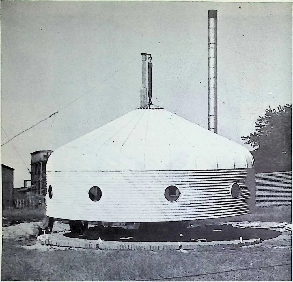
- 173.
- This picture represents ”a milestone episode’’ in Fuller’s experimental testing of his ‘‘comprehensive theories in environment controlling.’’ Here the first and second tiers of body sheets have been added to the suspended roof, and hung together from a mast which protrudes through the large hole in the top of the D.D.U. —a hole which was later to accommodate a ventilator. The ring of bricks and its contained earth, together with the steel tie-downs for the D.D.U., leading to anchors buried in the earth below, are clearly visible. The picture was taken at noon, in mid-August of 1940, in Kansas City, Missouri, in the secluded test area of the Butler Manufacturing Company. Fuller had the structure hoisted in this position for the first time, awaiting the arrival of the Butler Company engineers, and the company’s president, E. E. Norquist.
235The temperature was over 100° in the shade. The metal of the building was so hot that it could scarcely be touched. The Butler engineers were greatly impressed with the neatness of the demonstrated theory. Norquist, a lifelong enthusiast for structural enterprise, suggested that the group go inside. ‘‘You’d better not do that,’’ said the engineer, ”you’ll burn up.’’ Norquist, with Swedish intransigence, entered. A few seconds later, he called out: ”It’s air-conditioned in here.’’
236The engineers thought he was joking, but followed him into the building. ”To the amazement of all,” Fuller reports, ‘‘it was truly cool—if not cold—inside. Cigarette smoke and the men’s faces told them that a vigorous, cold downdraft was operating at the center. Cigarettes were lighted, and the smoke patterns studied inside and out in an attempt to comprehend the atmospheric patterning that was invisibly in operation to bring about this surprising interior coolness under a scorching sun.’’
237What was discovered confirmed Fuller’s long-held theory that energy in gases evolves unique local patterning?.
238He reasoned that energies could be maintained within local patterns at heat levels quite different from the heat levels of the surrounding atmospheres, just as the Gulf Stream maintains a different heat level as a unique hydraulic patterning within the comprehensive ocean pattern. If energies could be retained locally, by atmospheric patterning alone, local environment controlling for man might be accomplished even without visible walls. Visible shells, he saw, could be shaped to complement the inherent atmospheric self-shaping. Turnip-shaped shells would complement the horizontal doughnut. When a smoke ring ”evolutes’’ at its top, it must be involuting at its bottom. If such a ring were turned upside down, it would be involuting at its top, and ”evoluting’’ at its bottom.
239Fuller’s experiments disclosed that compound curvature systems provide energy’s No. i differentializer. Energy concentrations, such as the sun (in the picture) on the convex side of the system (roof), result in the radiation from the energy concentration being diffused by the convex surface.
240In this picture, the sun radiation (diffused into the atmosphere around the D.D.U.) is heating the atmosphere, causing it to expand. Hence it weighs less, and floats upward, initiating a rising thermal column around the Deployment Unit. This thermal drafts air from around the building to satisfy the upward flow, pulling the air from underneath the raised building, as well as from the surrounding area. This phenomenon, in turn, causes air from the top of the structure to be pulled downward inside the structure (through the ventilator at the top) to satisfy the partial vacuum created by the exhausting of air from under the structure. Also a cold draft spirals downward through the central core of the rising thermal and is drawn in through the top ventilator. The downward spiral of cold air inside and the energy-exchanging rising column of warm air outside together account for energy dissipations as heat. The result, predicted by Bernoulli’s principle, is a natural interior cooling system. When the energy concentrations are on the outside of a convex system, they cause an interior involuting torus of the atmosphere. That is to say, the air immediately adjacent to the hot skin on the interior, rises rapidly as a miniscule boundary layer; and all the rising airs converge at the top, to be vacuum-drafted downward, thinned, and cooled in the process. When the predominant energy concentration is on the concave side of a system, the energy released causes an ”evoluting’’ of a centrally rising, expanding, outward air flow at the top; and exterior downflowing with return to center at base of the atmospheric torus pattern, to feed again upward into the ”evoluting scheme.’’
241Fuller saw that the involuting or-evoluting patterns of atmospheres could be used to provide cooling or heating efficiencies, respectively, if he would provide complementary shell shapes, proper venting controls (top and bottom), and introduce small amounts of energy into the controlled local patterning. The demonstration confirmed his 1927 assumption of ”interior and exterior aerodynamics as a fundamental of the essentially invisible design problem of environmental controls.’’
242However, despite Fuller’s knowledge and exposition of the thermal column phenomenon, he finds today that dome users still tend to think of heated air only as everywhere rising. They put large ventilating fans at the zenith of their domes, and in the summer set a fan in motion to pull the air upward and outward from their domes. This simply frustrates the natural tendency of the air to flow downward and outward at the bottom of the dome. The result is that energy as heat stays impounded within the dome.
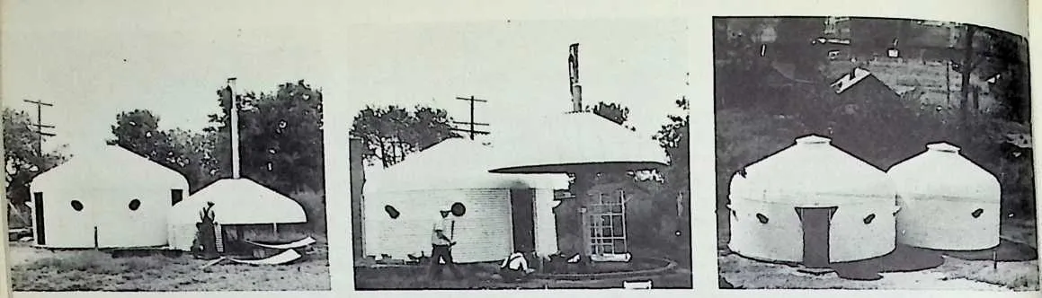
244245174 In this picture, unit No. 2 of the ‘‘twin cylinder’’ D.D.U. is being started. The mast has been removed from No. i, and repositioned to elevate cylinder No. 2 (1941).
24617S The roof of No. 2 is completed and elevated. Below it is the door by which cylinder No. 2 will be close-coupled to cylinder No. I. Immediately below the roof of cylinder No. 2 is the box chassis and partition framing of the unitary bathroom-kitchen assembly.
247T76 Cylinders Nos. I and 2 completed.
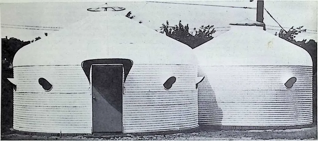
- 177.
- The adjustable translucent ventilators at the top of the D.D.U. are shown partially elevated; they could be opened 18 inches more.
- 178.
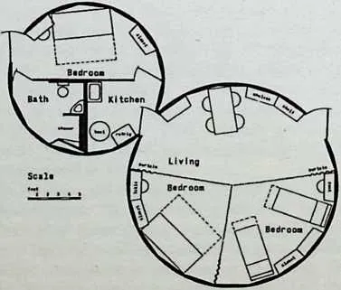
- Plan of the twin-cylinder D.D.U., providing a three-bedroom layout with bath and kitchen utility unit which served as a partition for one bedroom. Curtain partitions divide the larger cylinder into two bedrooms and a living room.
- 179.
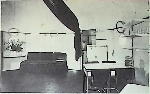
- Interior of Twin Deployment Unit. The large cylinder in daytime functioned as a 20-foot living-kitchen room. Note the plug-in electrical strip forming entire circle around interior of the dwelling unit at head of keyhole strips. Electrical appliances could be plugged into the strip at any point.
- 180.
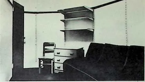
- Bedroom in the small D.D.U. twin cylinder. The partition at left is the T-head partition on the utility unit.
253 ivmim
- 181.
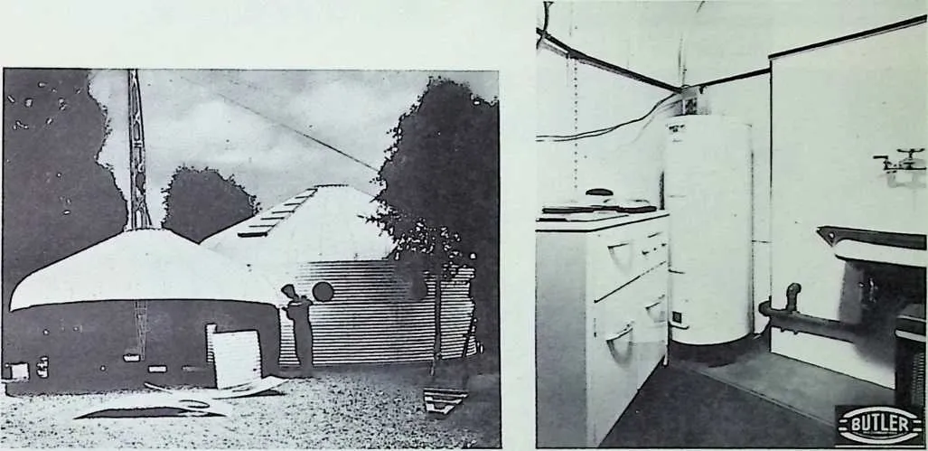
- Twin Dymaxion Deployment Unit being installed in the garden of the Museum of Modern Art, New York City, in the summer of 1941. Note the metal masts and their integral winching apparatus. These became standard items in the packaged unit delivered to the Armed Services.
- 182.
- Kitchen side of utility unit with its electric hot water tank.
- 183.
- Cluster of D.D.U.s installed at the head of the Persian Gulf during World War II as dormitories for aviators and mechanics assembling American pursuit planes for delivery to Russia. These units were individually air-conditioned and lighted by electrical hook-up with the generators of a ship permanently moored at the local dock.
254 DYMAXION DWELLING MACHINE
255 184 Ventilator for Dymaxion Dwelling Machine.
- 185.
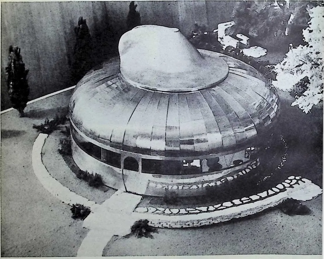
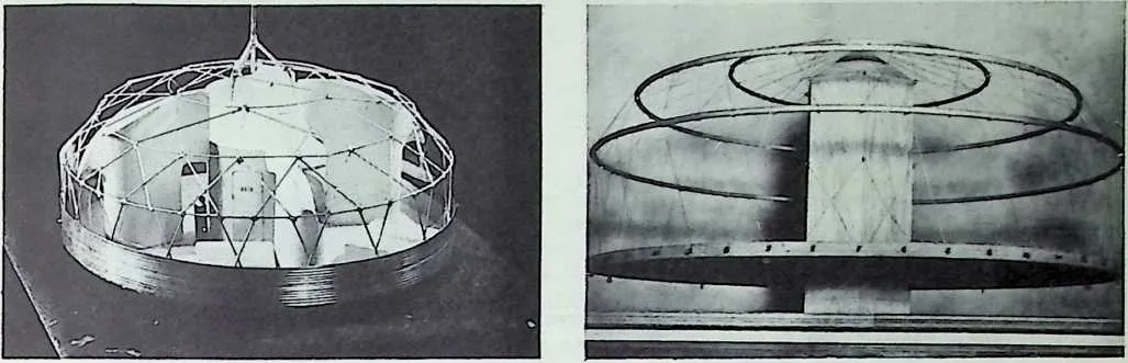
- An early model of the Dy maxion Dwelling Machine (Wichita House). The mechanical equipment was designed to be placed inside these aeronautically-faired space dividers. (1944)
- 186.
- After the external torus shape of the environment controls was established, Fuller’s parallel wire-wheeled structure was developed.
- 187.
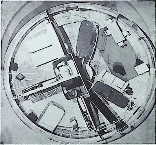
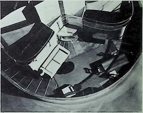
- View showing the Dwelling Machine’s rooms: two bedrooms, two bathrooms, kitchen, entry hall, and living room. The oval pattern of the mechanical enclosures permits a smooth, non-cornered circulation, and a diamond-shaped living room, whose long diagonal was 28 feet.
- 188.
- Living room area with two balconies and central stainless steel fireplace.
- 189.
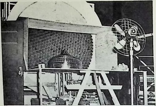
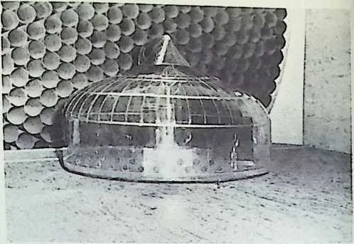
- An early model of the Dy maxion Dwelling Machine mounted on scales at the mouth of a Venturi wind tunnel. It was mounted to provide a surrounding aeronautical pattern similar to the pattern around a turnip-shaped gasoline storage tank on the Kansas prairie, (which had been carefully charted). Fuller was aware that air motions around structures close to the ground differ greatly from those formed around an airplane in flight. Wind motions near the ground resemble water motions at river bottoms which dig out orderly waves in the sand. Big air waves make enormous sand waves in the deserts. With these effects in mind. Fuller attempted to determine the minimum drag effects on buildings. (1944)
- 190.
- Close-up of the model at the mouth of the wind tunnel. The model was transparent so that colored gases introduced into air stream could make visible both the interior and exterior air patternings.
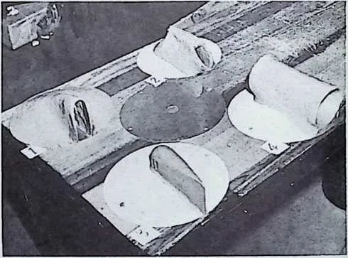
- 191.
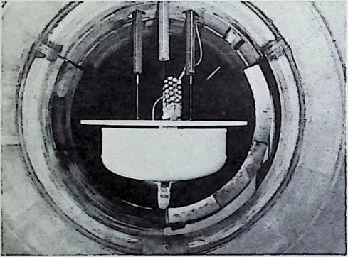
- Having weighed the drag on the model, at the Venturi tunnel’s mouth, Fuller suspended a hard model upside down at the center of the tunnel. Wind speeds from 25 miles per hour up to those of double hurricanes, were studied. Tubular connections were made to the ventilator which is shown upside down in the picture above. The low pressure drag focus of the structure was so controlled as to occur always at the exit from the ventilator. The vacuum drag caused by air motions about the building was thus utilized to pull directly on the ventilator’s exhaust.
261Because ”pulled airs’’ may be pulled around any curves (in contrast to ‘‘pushed airs,’’ which tend to turn back on themselves), the draft flow pattern is subject to control flows through a building from opening vents placed anywhere around the building. Thus, it was found that air could best be pulled in below the building, and made to complement the interior aerodynamics for heating or cooling purposes. Vacuum registers around the floor edges of the Dymaxion Dwelling Machine automatically sucked away dust or scraps swept close to the registers. Wind tunnel tests showed how much vacuum would occur at the ventilator exhaust at various velocities of air motions outside the building.
- 192.
- Many types of ventilators were attached to the bottom of suspended dwelling machine models until those were found which provided minimum drag and most exhaust usefulness.
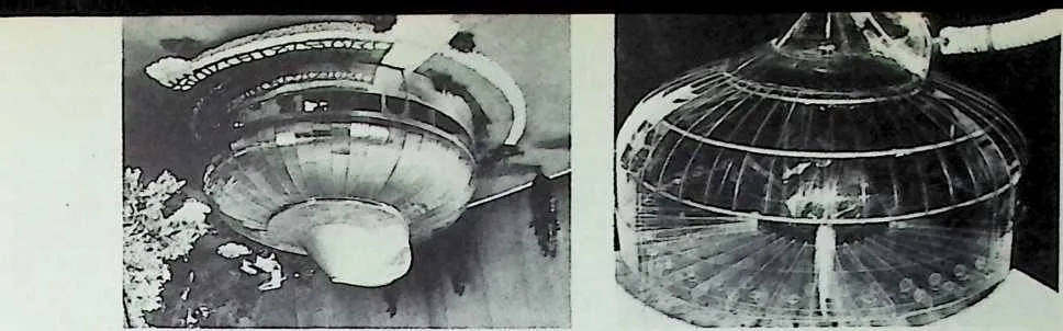
- 193.
- Ventilator, of a design that provided minimum drag and maximum exhaust effectiveness, is shown upside down. Its shape is similar to a cruising sailboat hull and rudder. (This picture is shown right side up as 184.)
- 194.
- A vacuum hose was attached to the exhaust opening of the ventilator to pull the interior atmosphere over preferred circuits. These air circuits were governed by inlet holes around the bottom of the Dwelling Machine’s cylindrical shell, and by holes in its bottom at the center. By introducing colored gases below the Dwelling Machine, when the vacuum tube was pulling on the ventilator, Fuller found that air would rise through the structure’s central cylinder, completely bypassing the dwelling area, and going out the zenith exhaust. Alternately, the air could be made to rise through the central cylinder, entering the top of the dwelling room area, thereafter being pulled (1) down to perimeter floor exhausts, (2) through floor ducts to a central interior column, and out and up to the main exhaust. This arrangement permitted the pulling of cold air in through ducts on a lower face of an aluminum floor heat exchanger, pulling the air upward in the mast to be heated by a central ‘‘solar’’ system; then out and down through the room to counter cold drafts adjacent to the window surfaces. The air would then pass into the aluminum heat exchanger floor ducts to transfer its heat loads through the duct surfaces to the incoming cold air on the other side. In this way, Fuller developed a complementary evoluting torus. The upward evoluting exhaust column conserved the heat within the structure in cold weather, just as the downward involuting central column, exhausting at bottom perimeter and fed by zenith intake, provided a natural cooling system in hot weather.
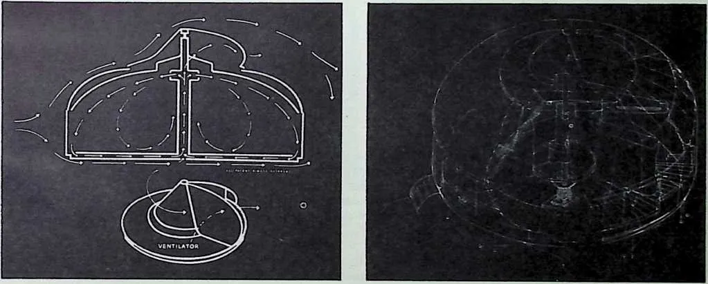
- 195.
- Diagram showing how the external air flow, traveling its greatest distance over the top of the structure, created a vacuum drag at the ventilator, which in turn dragged the internal air flow pattern. Not shown are the two central cylinders, one smaller and concentric to the other. The incoming air was drafted upward through the large cylinder. Exhaust air pulled from the rooms was drafted upward through the smaller cylinder. Thus the incoming air was never polluted by the exhaust air, even though the exhaust air lost its heat through the metal baffle to the incoming air.
- 196.
- Final general assembly of the Wichita Dwelling Machine structure and mechanical complex. The drawing shows the heavy coil springs at the mast base on the ground shoe which received shock wave impacts on the structure. The total structure was tied down by vertical and diagonal tension cables fastened to anchors at the base.
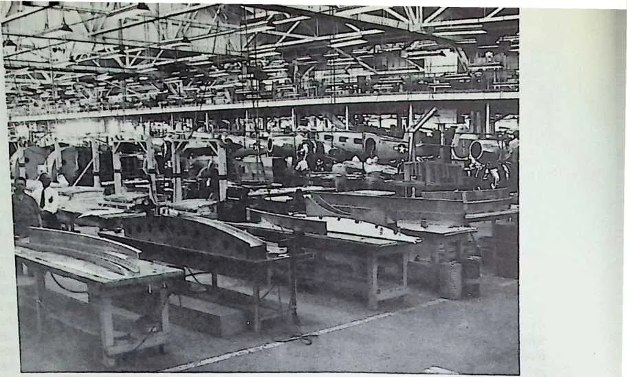
- 197.
- View on main assembly floor of Beech Aircraft, showing the production line of twin Beech planes (far side), parallel to the production line of Dymaxion Dwelling Machine parts (left foreground). (1945)
- 198.
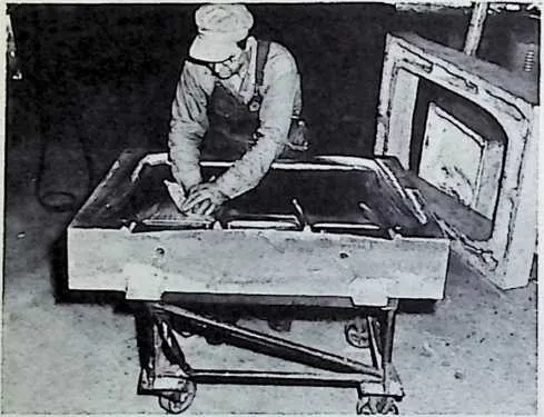
- Soft tool production of the Dymaxion Dwelling Machine (1945) took advantage of the unique tools developed by the aircraft industry with the implicit assumption that ”change is normal’’; such tools were intended to be used only for limited runs. Shown here is the male half of a Kirksite drop-hammer die. Kirksite consists chiefly of tin, whose low melting point is a factor in short-time-period tool development. First step in preparing such a tool is the construction of a clay model, from which plaster casts are made. Sand-cast models are quickly formed from the plaster casts. The solder-like Kirksite having been easily and quickly melted is poured into the sand-cast models. Kirksite dies can be dressed-down to preferred tolerances simply by sandpapering, as shown in the picture. Although the United States has no economically workable tin ore in its known geology, it has a stock of tin from Malaya, Bolivia, and Tanganyika, in the form of Kirksite dies Standing in its aircraft industry storage yards, ready for re-working into new dies. The total tonnage of this tin is possibly greater than that still existing below ground in the world’s far-flung tin mines. In effect, the U. S. has the largest aboveground tin mine in the world. And in this mine, the metal is continually put to good and better uses.
- 199.
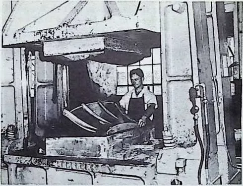
- Male and female Kirksite dies, mounted in drop-hammer, transform an aluminum flat sheet into ventilator apron component for the Dymaxion Dwelling Machine. This component joins the ventilator cone to its 18-feet skirt. Parts were produced within 24 hours of completion of drawings.
- 200.
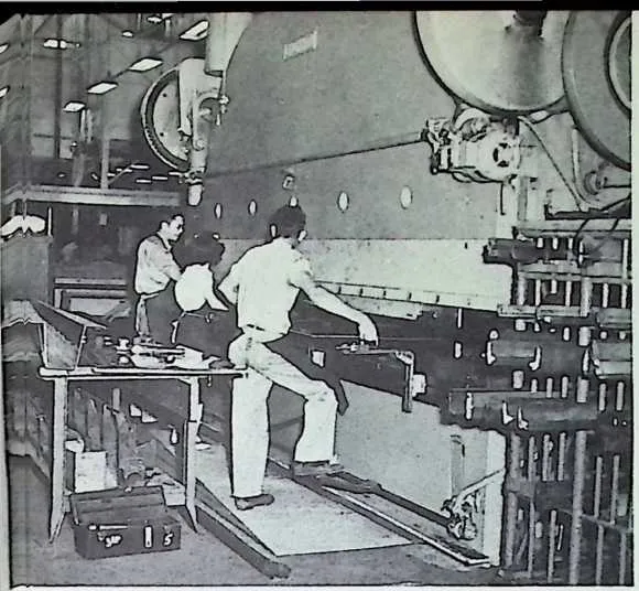
- Large press brake, transforming flat aluminum sheet into 14-foot, tapered floor beams of the Dwelling Machine, one of which is shown on table top at left.
- 201.
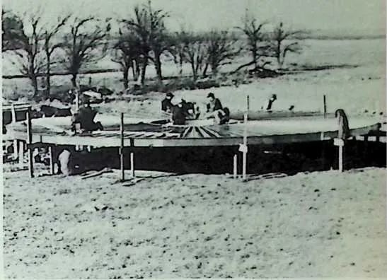
- Complete array of tapered trough floor beams installed in annular, aluminum Z-ring as floor support of Dwelling Machine.
- 202.
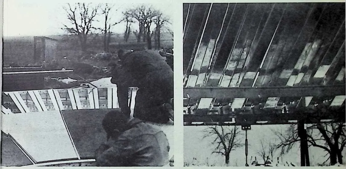
- Top surface of the floor troughs used for exhaust air conduction from the interior perimeter of the floor area through cove registers. The underside of adjoining floor beams provided the conducting chamber through which incoming cold air was led to central mast. Plywood pie-shaped floor units were superimposed on aluminum floor ribs; they were locked down by ‘‘fish-hook hat section” floor joint runner strips, which caught into a trough between the floor ribs, and provided a slide angle into which pie-shaped floor pieces, with beveled edges, were driven like wedged corks. As in the Deployment Unit, Fuller developed a complete floor without using screws, nails, or cement. Result: a completely dry, demountable, muscularly-tight system.
- 203.
- Underside of the aluminum floor beams, each of which weighed only 10 pounds. Shown are the ducts through which incoming cold air was led.
- 205.
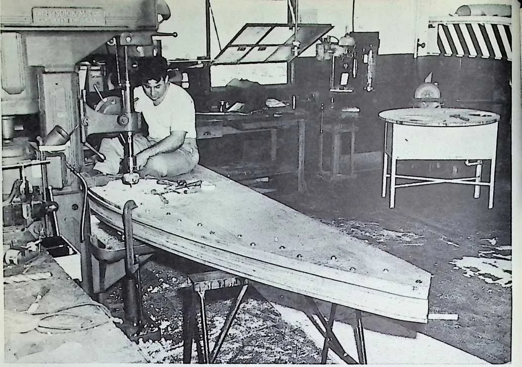
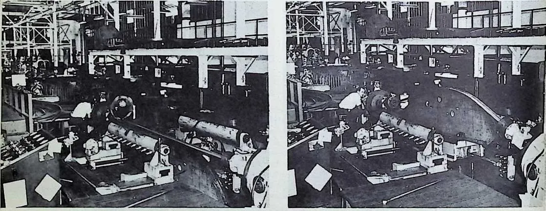 The wood die (lower right corner) is mounted into a
hydraulically-actuated tool complex, whose operator stands at lower left
in front of his electrical console control. Another workman is shown
attaching one end of a 6 X 4 inch X 14 feet ‘‘hat section” strip of 24 S.T.
aircraft alloy aluminum. The strip is turned upside down in the picture
and looks like an aluminum gutter. Both ends of this straight piece are
clinched in great hydraulic fists, called chucks, in such a way that the
gutter mid-part sits in the hardwood die groove.
268 204 Only those tools unique to the aircraft industry are shown in this series. Shown is the wood die, a typical aircraft industry soft tool, used for the forming of roof ribs of the Dymaxion dwelling machine.
- 206.
- The wood die rises, actuated by the console controls, while the universal-jointed giant fists stretch the metal gutter piece like taffy around the wooden die’s elliptical groove perimeter.
- 207.
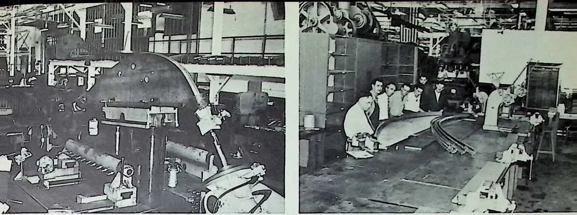
- The stretch press in the final forming position. The gutter piece has been stretched to conform to the elliptical die.
- 208.
- The 2-pound formed ribs are checked at the inspector’s station for trueness of curvature.
- 209.
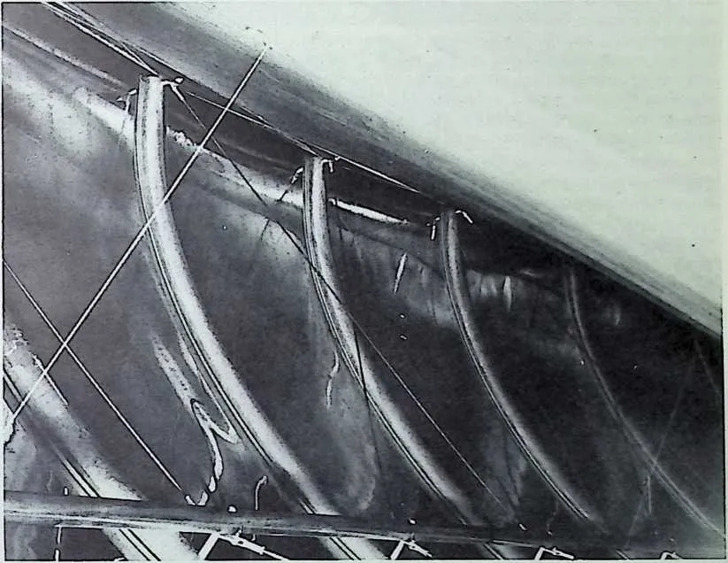
- View inside the domical roof of the Dymaxion Dwelling’Machine with the compound-curved, 2-pound, ”hat-section” ribs in place supporting the outer skin. The function of the ribs was primarily to support the roof, and any of its live loads, while at’ the same time acting as gutters for whatever water might leak through the joints of the aluminum sheet gores comprising the roof’s skin. The closely butted edges of the roof gores occurred directly above the center of the gutter; and the gores were pulled so tightly around the ribs that any moisture coming through the joints could lead only into the gutters. These gutters led down to Neoprene gutters running around above the window height of the Dwelling Machine, internal to the structure. Any moisture or condensation inside the roof ran down to this gutter or dripped onto the fiberglass-Neoprene tent (shown in lower left hand corner) which lined the Dwelling Machine. Water coming down this skin was also led to the Neoprene gutter. All the internal gutters led through Neoprene tubes to soft rain water storage tanks. The inter-roof space could be used as a condensing machine to take the moisture out of the air in rion-rainy weather.
- 210.
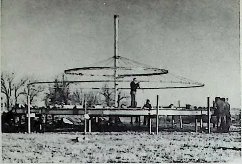
- Assembly of the Dymaxion Dwelling Machine began with the installation of the floor ring and radial beams, and the erection of the structure’s permanent mast, mounted on a central shoe and springs. The delicate tensile, tie-down diagonals and verticals can be seen reaching from underside of floor beams, to anchor heads buried in earth. Each of the 12 anchors could resist an upward pull of 12,000 pounds. The 22-foot mast was formed by seven 3-inch stainless steel tubes clustered in closest packing. The hexagonal bundle thus formed was strapped parallel with stainless steel horizontal straps every 18 inches. The 22-foot tubes weighed a little less than 10 pounds each. The total weight of the mast, with straps, was only 72 pounds. The cactus-like, vertically fluted mast was designed and tested to carry not only the dead and live roof loads of the building, but also the weight of 120 occupants. Shown in the picture are the A-, B-, and C-rings which were the circular rims of the horizontal, wire-wheel complex. These rings have been interconnected by the high-carbon tension spokes. The B-ring, which sustained the heaviest compression thrust of the whole Dwelling Machine, was formed by tubular sections of stainless steel. None of the metals or other materials used in the Dymaxion Dwelling Machine needed to be painted or maintained. All were non-oxidizing. Dielectric gaskets were interposed between any metals which might develop electrolytic exchange, and consequent deterioration. (1945)
- 211.
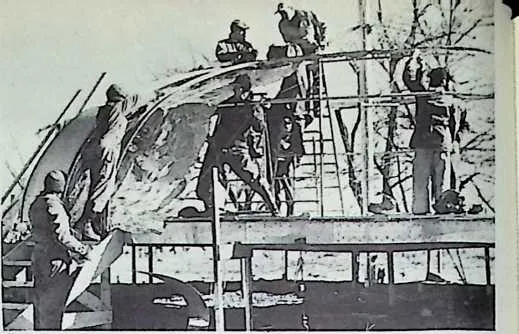
- The 2-pound ”hat section’’ ribs have been attached to the A-, B-, and C-rings by three bolts. Pictured is the aluminum foil sheeting being draped between the ribs; it served as a secondary radiation barrier between outer and inner skins of the Dymaxion Dwelling Machine. The workman at lower left is holding a partially coiled roof gore made from high alloy, heaMreated, aircraft aluminum, with strength characteristics approximating those of spring steel. At far left, roof gore sheet has been made fast at A- and C-rings. Two bolts catch the sheet at the C-ring, while one bolt at the A-ring pulls the gore sheet tautly around the ribs when the nut is tightened.
- 212.
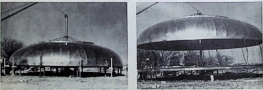
- All the roof gores in place. Sunlight reflection shows the hyperbolic compound curvature pulled into the roof gores. Shown also is the fine tolerance of the seams between the roof gores, which let any penetrating water through to the roof gutters.
- 213.
- The complete roof dome becomes a rigid unity, and is shown elevated to final position and tied down to Z-floor-ring by criss-crossing stainless steel rods. The intervening hexagonal openings between rods provided generous space for doors and other traffic requirements.
- 214.
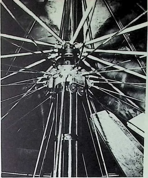
- View of central masthead, showing stainless steel forged cap piece of mast, into which seven 3-inch stainless steel tubes lead. The radial spokes of the dome were suspended from the forged ring and made fast with high-tension aircraft clevises. Also suspended from the forged cap were six ball-bearing sheaves (pulley blocks). Through these ball-bearing sheaves, a flexible steel aircraft cable was led in six parts, reaching upward and downward between similar sheaves attached above the mast cap. When this cable was winched in by an electric motor, it pulled the entire roof dome upward around the mast from its assembled position to its final position—with the smoothness of the curtain raising in a theatre. Shown above the masthead rings, spokes, and sheaves, are the tubular spokes of the 18-foot ventilator. The whole ventilator revolved on a Cadillac front-wheel spindle, roller thrust bearing. ”Although this complex of jewelrylike, non-rustable alloy components appears to be expensive,’’ said Fuller, ‘‘it did so much with so little (and its total poundage was so small) that Beech Aircraft was able to make firm proposals to soft-tool manufacture the Dwelling Machines at a cost of only $1800 each.”
- 215.
- The extensible boom of a special assembly truck was attached to the masthead as safety measure—when the first group assembly was intentionally erected in gale velocity winds. Experiment showed that the structure, partially-assembled, could handle its own stresses without aid of the boom anchor. In this picture, temporarily paper-coated Plexiglass window sheets have been hung below the C-ring and gutter, and the Z-section window sill has been suspended by riveting to bottom of plastic windows.
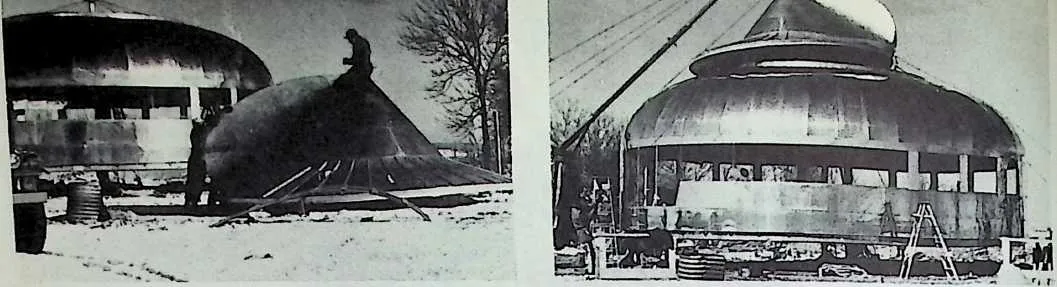
- 216.
- Complete 118-foot Plexiglass window has been installed. Below the window are slide-skin cylinders, designed to form two halves. The top horizontal half below the window dropped down in 12-foot curtain sections outside the lower half, providing a screened ventilating opening, 12 feet long, 18 inches high, below every two windows. All of the slide-skins could be opened simultaneously, providing an 18-inch. high ventilating opening, 118 feet long, running completely around the Dwelling Machine. This screened ring was designed to implement the hot-weather, cold-down-draft natural air- conditioning of the structure. At right is shown the 18-foot ventilator and its pair of tail exhaust fins.
- 217.
- Ventilator hoisted by a boom to masthead-mounted spindle support. The entire ventilator could be raised by masthead mechanism to a position 3 feet above the central, top roof ring, whose 18-foot-diameter opening was screened. If a sudden low pressure area engulfed the structure as in the case of a tornado eye or a major explosion, the 18-foot ventilator would ride up its 3-foot spline, acting like the exhaust valve on a steam boiler, and effectively relieve the relatively high internal pressure.
276The marriage of the hyperbolic parabola curve fins to the conic front of the ventilator, and the broad, 28-square-foot opening tail exhaust of the ventilator, provided a structure that rotated like the broad-tailed tetrahedrons used for airport wind direction indicators, the tail form serving (as with broad-tailed bullets) to. spoil flutter-causing oscillations of low pressure differences on either side of the tail surfaces. The Dymaxion Dwelling Machine ventilator always headed steadily into the wind.
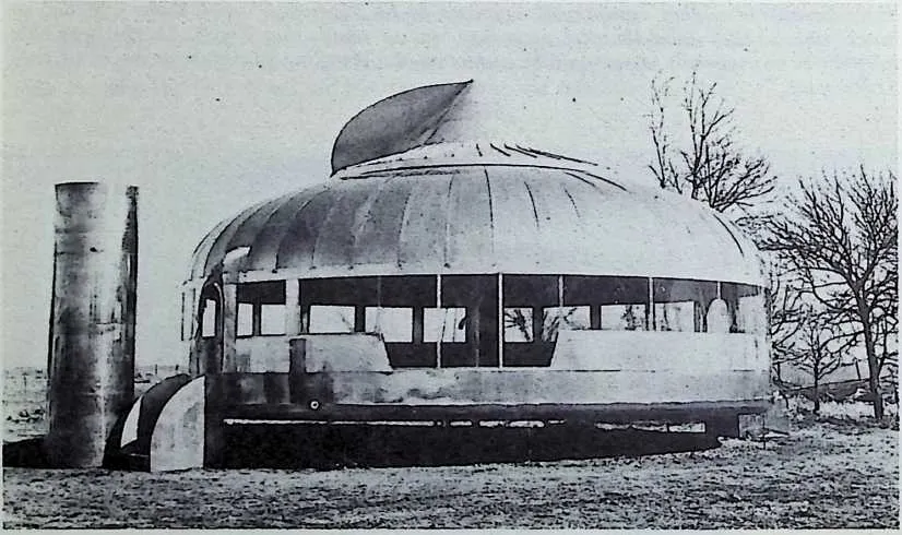
- 218.
- Final assembly of Dwelling Machine completed, showing long window sections in living room area. The bottom gutter is in place, leading to main rainwater system. The vertical cylinder, at left of hand-hold gangway, contained all component parts of Dwelling Machine. Parts were assembled around a central spindle and inserted into the cylinder for shipping. Rolling rings capped both ends of the cylinder. The total structure weighed approximately 6,000 pounds. This figure agreed with Fuller’s 1927 estimate of the weight of Dymaxion House of the same dimensions that could be realized when the interim alloying research had been completed. (1945)
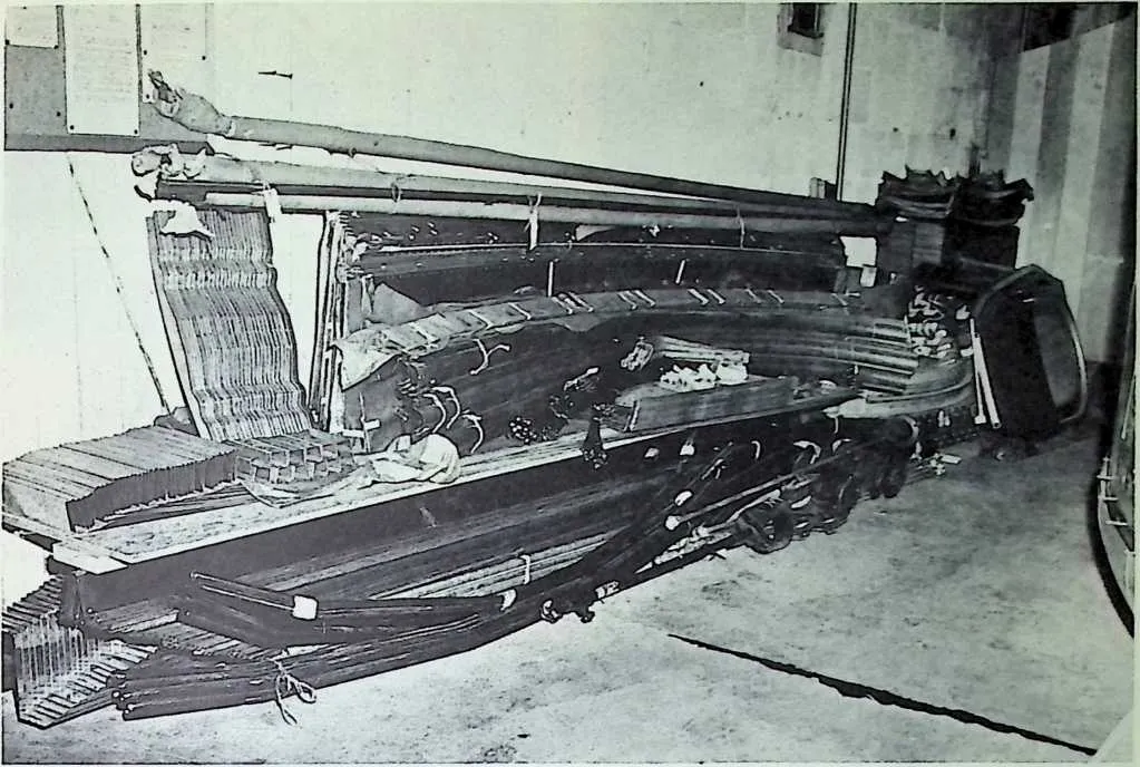
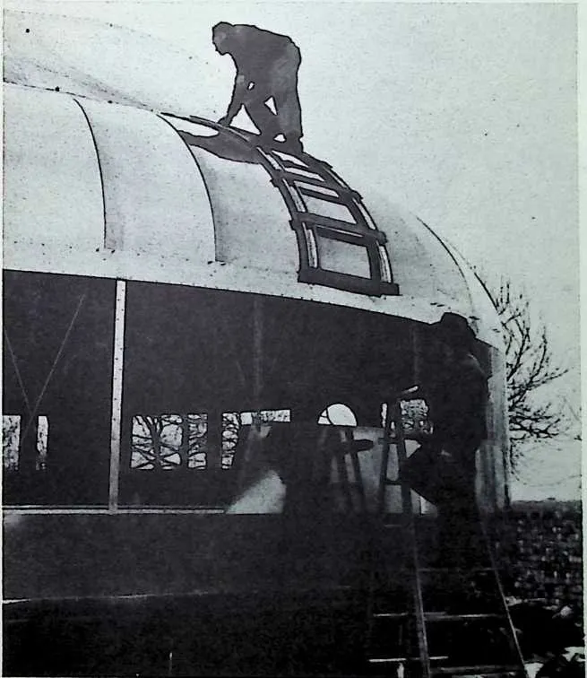
- 219.
- Total group of components of Dwelling Machine stacked before loading into cylinder. It was a fundamental responsibility of the design, as Fuller conceived it, to have all the parts compact to minimum cubage. Most parts were designed to nest together. No single part of the structure weighed more than io pounds. Any’single part could be handled by one man with one hand, leaving his other hand free to fasten the part in its place; consequently it was never necessary for any workman to require the services of a helper.
- 220.
- Eight-pound scaling ladder made from two roof ribs supports a man making ventilator adjustments. Hyperbolic curvature of the roof sheets is clearly visible. At bottom and lower right are bricks and stones ready to be loaded on the living room floor to simulate the weight of 120 people clustered on one side of the building—equivalent to eccentric occupant loads under full hurricane or earthquake conditions.
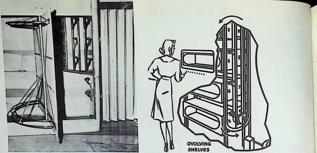
- 221.
- The door between the bedrooms was a tensionally-supported ‘‘modernfold” door, similar in appearance to Fuller’s 1927 pneumatically-inflated, vertically-fluted, sidesliding curtains. Note the Z-section aluminum window sill which developed the horizontal stiffness of the Dwelling Machine vertical wall. Double Plexiglass panes were riveted to it withj/binch space between their concentric, cylindrical sheet surfaces. Fabricoid material buttoned below window.
- 222.
- Pater-Noster-like ‘‘ovolving” shelf-containers, mounted on a continuous chain behind the partition wall. The opening in the shelf-containers registered with a horizontal opening in partition wall, at a height convenient for adult reach-in, but too high for small children. Pressing a button at the side opening caused the shelves to rotate past the window until the desired shelf was in register. Such ‘‘ovolving’’ shelf storages in each of the bedrooms, provided shelf space equivalent to an 18-foot stack of shelves of the same width. Although limited to 18 feet for the Dy maxion Dwelling Machine, these shelves could be of any height (hundreds or thousands of feet), and could provide for quick reference storage of major library archives.
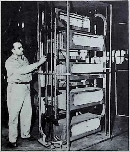
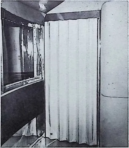
- 223.
- Production model of ‘‘ovolving’’ shelves, before oval skin of the storage partition was applied. The shelf elevator mechanism was driven by an electric motor.
- 224.
- Fuller developed revolving, vertical clothes hangers and semicircular shoe and hat racks, all mounted on the vertical central shaft of a centrally-pivoted partition panel.
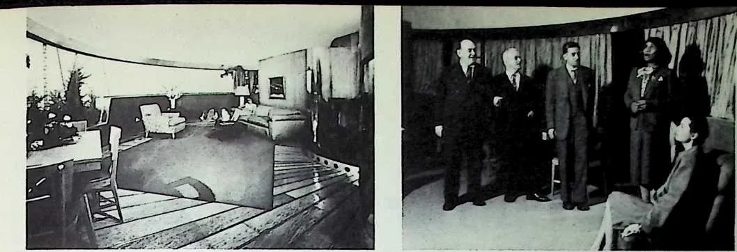
- 225.
- Interior view of the living room of the completed production model Wichita House, showing 37 feet of Plexiglass window in living room area. Also shown is the interior of the Fiberglass-Neoprene ceiling skin, upon whose neutrally-silvered surface, controllable color light was projected indirectly from the oval drum heads of partition units.
- 226.
- Musicians were impressed by the Dwelling Machine’s acoustics. Marian Anderson, after singing in the Wichita House, declared she had never before heard ”sound in the round” without reverberation or distortion.
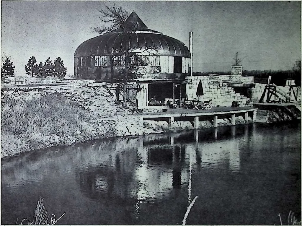
- 227.
- Lacking the 10 million dollars necessary for tooling the Dymaxion Dwelling Machine for a 20,000-units per-year production, the development ended the Wichita experiment. Two prototypes were ordered by the Air Force and later resold to Fuller’s project. They were ultimately acquired by a Kansas oil man, who combined them to form the house shown above, sans rotating ventilator. ”His architectural additions and modifications in effect,’’ said Fuller, ”forever grounded this aeroplane.’’
- 228.
- An early chart of Energetic-Synergetic geometry. Fuller holds that synergy is to energy what, in the calculus, integration is to differentiation. Energetic studies of nature differentiate out or isolate unique local functionings. Synergetic, studies seek to organize and comprehend the complex co-operative patterning that exists, a priori, in nature.
SYNERGETIC-ENERGETIC
284CoanneaUf r Caowlnly
285 Orpnlscd Plcnllty of Oftorlcal eaolaU. Extortor klllitla 2 TlMkla. 2 Javlolbla OiM*a
286GEOMETRY
287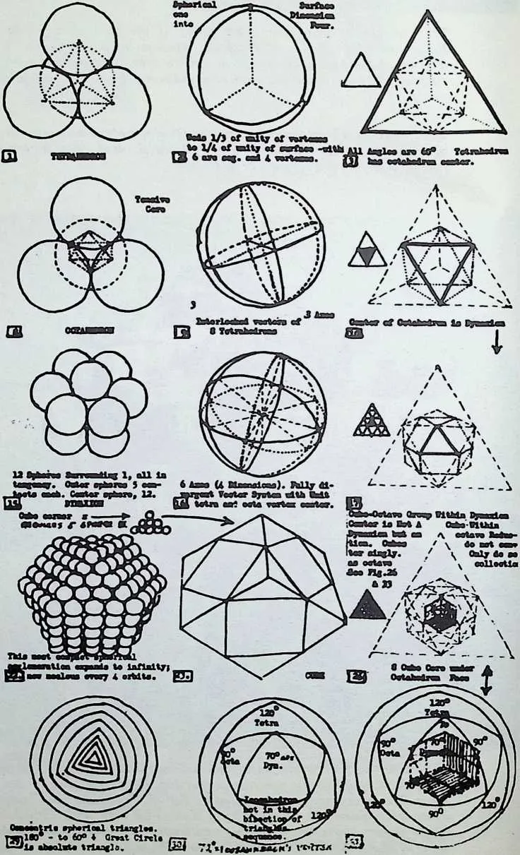 ”Synergetic geometry,’’ says Fuller, ”makes possible a childhood participation
in nuclear physics as a logical and enjoyable, rather than a precocious phenomenon.
However, scientific entry into the present realm of nuclear competence was
accomplished with the awkward, irrational tools of energetical strategy. The
development and adoption of the great computers has now relieved man of the
onerous tasks characteristic of the irrational constants interlinking the
many separate facts of scientific enquiry which arose from the energetic
approach. Because these tasks are being carried by the computers, and men are
getting along all right on their blind-flown scientific pilgrimages, there will
be only slow realization of the significance of the sensorially-conceptual
facility of dealing with nature that is opened up by the Synergetic geometry.’’
(1944)
288 Dlnigently Orjonltiod Olnslo Ofian -Interior Cccprooalca -Extorter Toaaloa, CdaiTlflca ty Omt ClrelM) ibaolota or o?a.f -crim voic cm tHolc1 Cslacc
289 Correct Hrot Ssirtlvicica e
290UlTWIOB.
291PcolUca in Srpor Totroiatan torasjjeot Ftoco of Toeton AU Vcrtaca cro Cjiartsal Cun
293CenwrnBt sad Dlmr*1 ”* hullml ValMS 1a H<b-L
294Oetaws
295Tcwad ORZKIKBl gessotrio Vector
296297
CowtnBOtlca in Equilibria. tti£3-Abcoluto CaavsjgCQCo first Ortit. vol. crith cakVti arfocq. Co Volr=,EztrlcT Ccrjircosica
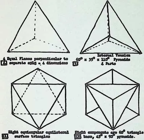
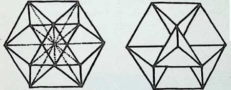
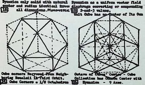
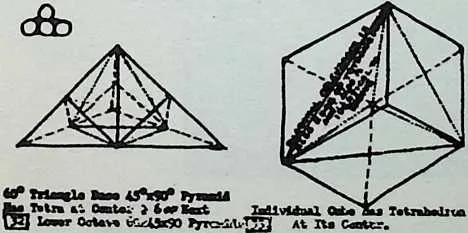
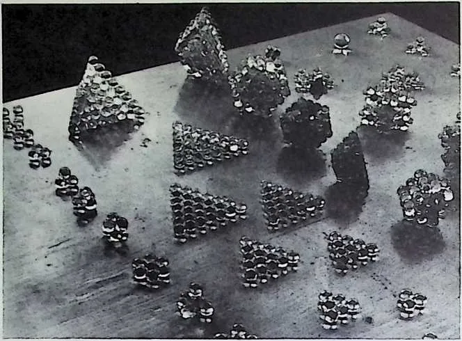
- 229.
- Topological systems always consist of lines, vertexes, and facets. When the vertexes of systems are identified by little spheres, and those spheres are enlarged, the spheres will gradually encompass the lines between the respective vertexes. If the expansion continues, the spheres finally become tangent to one another, and the lines are entirely inside the spheres. Shown in the picture are geometrical agglomerations of spheres, many of which correspond to the linearly-emphasized topological systems shown in the preceding chart. Fuller assumed that fundamental geometric patterns, which appeared successively as spheres were methodically compounded in all directions around one sphere, must have generalized constancy with respect to any nuclear patterning of the universe. He assumed that knowledge of the atomic nucleus could be discovered through such exploration in pure principle. Frequently, in recent years, nuclear principles discovered in mathematical geometry by Fuller, emerged in the integrated information acquired by nuclear physicists in their ‘‘particle’’ accelerator bombarding ventures, and their subsequent statistical accountings of the ballistic rubble.
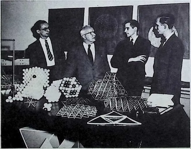
- 230.
- Fuller and research students, with closest-packing agglomerations of spheres in fundamental geometry, and a model of 25-great-circle sphere in process of assembly. (1948)
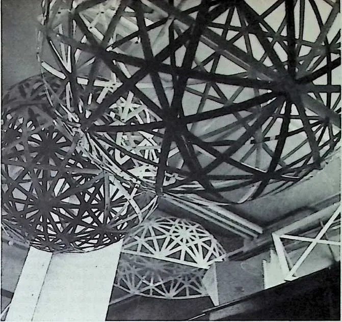
- 231.
- When systems are rotated on the axes defined by their vertexes, or the center of their faces, or their mid-edges, then great circle trajectories occur as ‘‘equators’’ of the respective axes of spin. These can be regarded as extensions of the interior planes of the system in respect to its nuclear center. The 25-great-circle pattern, shown in the largest sphere in the picture, results from the spinning of the Vector Equilibrium on all of its axes of symmetry. When the first direct photographs of atoms (taken through the Field Emission Microscope) were published in the early 1950s, the 25-great-circle whirling trails were to be seen, representing all the most economic degrees of freedom of action around a nuclear point. (This picture is also shown on facing page of chapter on Energetic-Synergetic Geometry.)
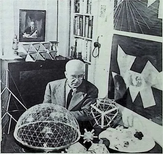
- 232.
- Fuller with his Energetic geometry models, Dy maxion map, Geodesic dome, Ten-segrity, and Octet Truss structures derived directly from Energetic-Synergetic geometry co-ordinations (Forest Hills, New York, 1951).
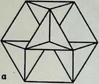
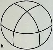
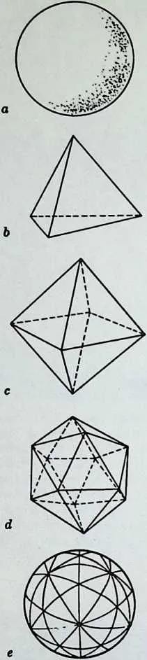
- 233.
- Shown here are: (a) Fuller’s model of the Vector Equilibrium showing internal planes formed by edges and radii (radial lines joining external vertexes to central vertex); (b) projection of the Vector Equilibrium on the surface of a sphere. Fuller calls the Vector Equilibrium the ”Grand Central Station” of ”the co-ordinate mathematical-physical system that is apparently the co-ordinate system employed by Nature to account most economically for its myriad transactions.”
- 234.
- Fuller defines the sphere (a) as ”a multiplicity of discrete events, approximately equidistant in all directions from a nuclear center.” The discrete points of such a system can be inter-triangulated. The tetrahedron (b), the octahedron (c), and the icosahedron (d) are the only possible cases of omni-equilateral, omni-triangulated finite systems. Pictured at (e) are the 15 great circles developing from rotation of the icosahedron in respect to the 15 axes interconnecting opposite midpoints of the icosahedron’s 30 edges. The 120 resulting right spherical triangles represent the maximum unitary subdivision of a one-radius system. This fact was long known in mathematics. Since 120 is 10 times 12, Fuller thinks that this geometric relationship may underlie both the decimal and duodecimal systems of modular accounting; and may have been derived by subdividing a finite system into its lowest common denominator. He believes that we inherited the combined decimal and duodecimal systems from this fundamental thinking in early Babylonian science and in the mathematical invention of the Sino-Indian navigators.
- 235.
- Fuller’s chart of ”constants of relative abundance” of the fundamental characteristics of topological systems when subjected to ”omni-triangulation and omni-consideration of the additive and multiplicative twonesses of all finite systems.” Fuller’s basic theorem: The difference between the sum of the angles around all the vertexes of any finite system and the number of vertexes of the system times 360 degrees, is always 2 x 360 degrees. This is to say that the difference between finite systems and infinity is the sum of the planar angles around two points, each of which lies in its separate plane, parallel to the other. When angles around points add up to more or less than 360 degrees, convexity and concavity result. In short, Fuller shows that the difference between finiteness and infinity is 2.
303304The inherent disparity of convexity and concavity introduces an inherent multiplicative twoness. As the chart shows, Fuller found that the ”additive twoness” is that of the two polar points. The ”multiplicative twoness” is that of the inherent disparity of convexity and concavity. When the additive twoness and the multiplicative twoness are extracted from any symmetrical and omni-triangulated system, the numbers of vertexes will always be a rational product of one or more of the first four prime numbers: I, 2, 3, and 3. The number of faces will always be twice that of the vertexes minus 2; the number of edges will always be three times the number of vertexes, minus 2.
305 MAPS AND CHARTS
306236 Fuller’s 1927 mimeographed picture of the ”one-town’’ Air Ocean World. His working assumption of air delivery of his 10-deck buildings to the world’s remotest and environmentally most hostile places implemented his program for a world integrated by air traffic between stepping-stone maintenance points and over previously non-feasible routes. Note the airplanes flying the Northwest Orient flight between the U. S. and China; the Dakar-Natal, the trans-African-trans-Siberian, and the Inter-American flights. No such operated air routes existed at the time of Fuller’s drawing—which was the year of the Lindbergh flight. Tflis world picture (shown previously as 20) was the start of Fuller’s comprehensive design thinking in relation to the resources and world peoples.
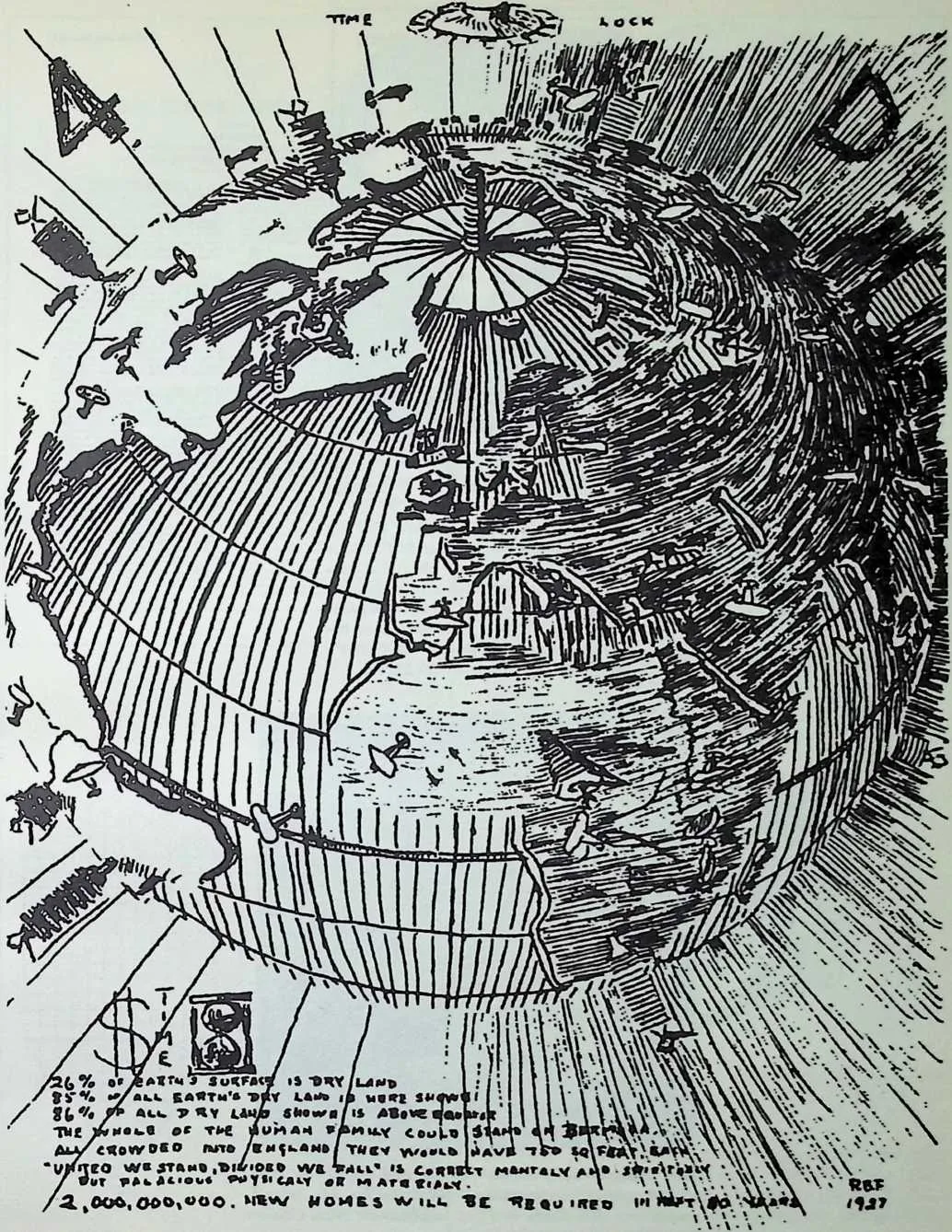
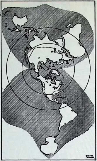
309237 World map roughed out by Fuller from globe as a test of his ‘‘intuitive realization’’ that this patterning arrangement could be derived from exact mathematical processes (1936). The map was reproduced as end papers in Fuller’s book, Nine Chains to the Moon.
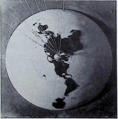
311238 Model of Fuller’s ‘‘one-world island in one-world ocean’’ constructed for him by his friend, puppeteer Bill Baird in 1937 to illustrate Nine Chains to the Moon.
312 Pnixr-cJ Jon. 20, 1043
3132393,676
314 UNITED STATES PATENT OFFICE
315 Jan. 29, 1946.
316 2,393,676
3175 Sbeat-Shcot 1
318 R. B FULLER
319 CABT03BAFHT
320 Filed Feb. 25. 1344
321239–242 Pages from Fuller’s U. S. patent covering the Dymaxion map. Science referred to this as ”the first cartographic patent to issue from the U. S. Patent Office.” (Top right is also shown on facing page of chapter on Cartography.)
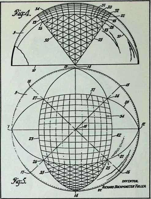
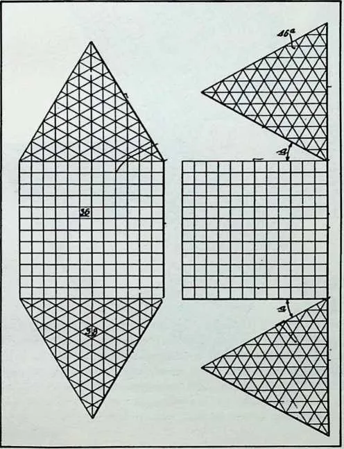
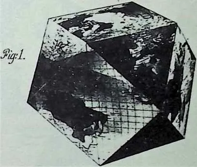
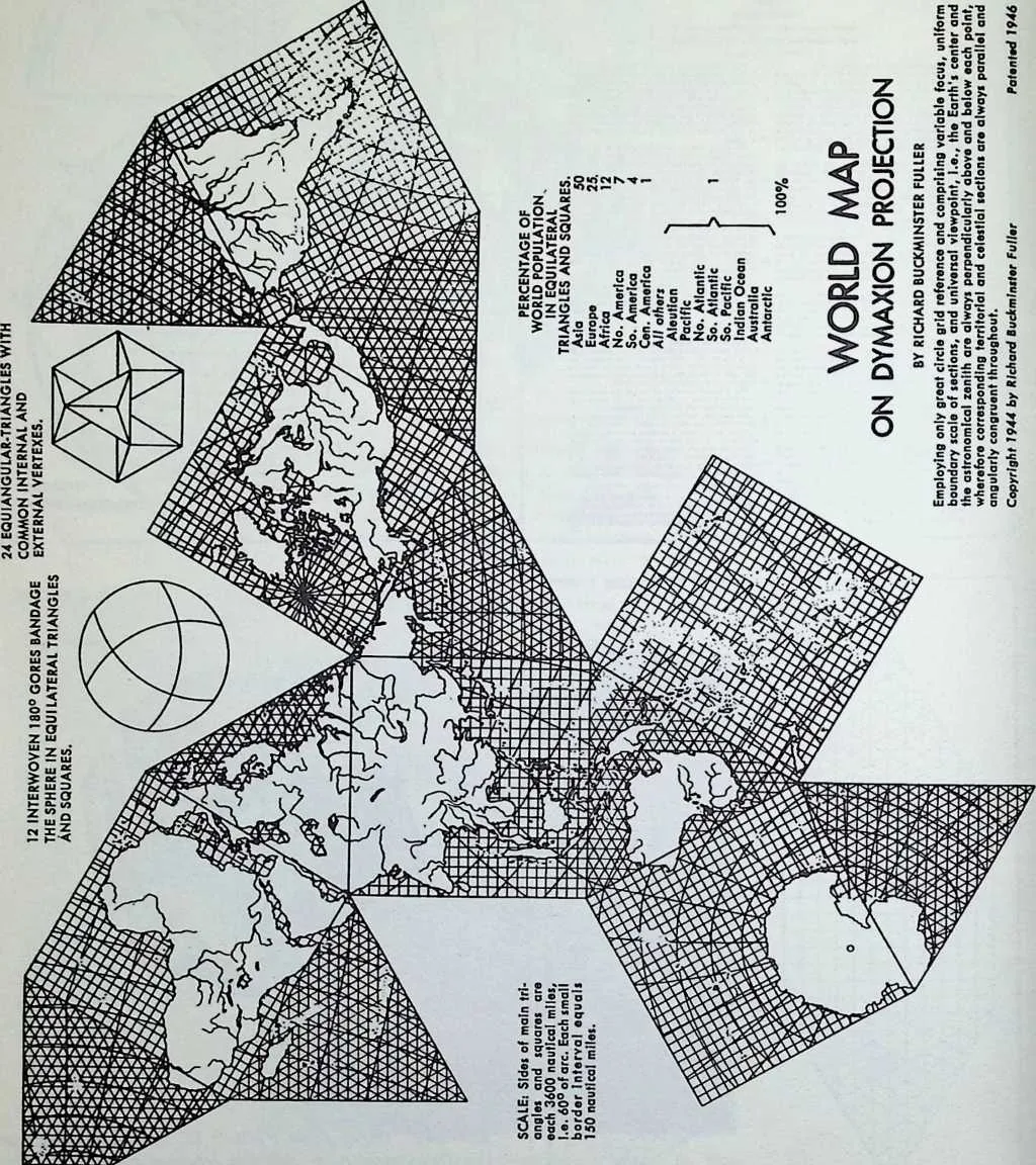
324 ONE CONTINENT
325 Bottom of th© Areonouticol Ocean
326 EAST BY STEAM TO THE ORIENT VIA SUEZ
327 ONE OCEAN
328 Admiral Mahan named it.
329 The British discovered and used It.
330 EAST BY SAIL—TO THE ORIENT VIA GOOD HOPE From the Spanish Main via the Piratical Indian Waters. 12,000-mile great circle route from New York to Australia.
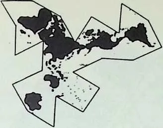
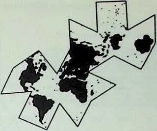

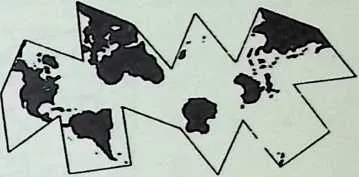
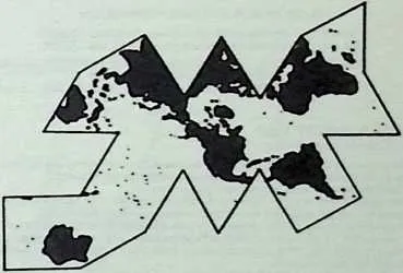
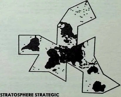
333 NORTHWARD TO THE ORIENT AND NORTHWARD TO EUROPE
334 Old and new worlds on either hand.
335 Russia overhead and McKinder’s World Island trisected.
336 European triangle controls the altitude merry-go-round.
337338244–249 Closeups of special sectional arrangements of the Air Ocean World Map.
339243opposite page;the 1944 edition of Fuller’s Air Ocean World Map which displayed for the first time on one surface all the world’s geographical data without visible distortion of the relative shapes or sizes, and without any breaks in any continental contours. The pieces could be mounted together as a Vector Equilibrium, or assembled in a variety of ways, each emphasizing unique world geographic relationships.
340341Conservation of Resources
342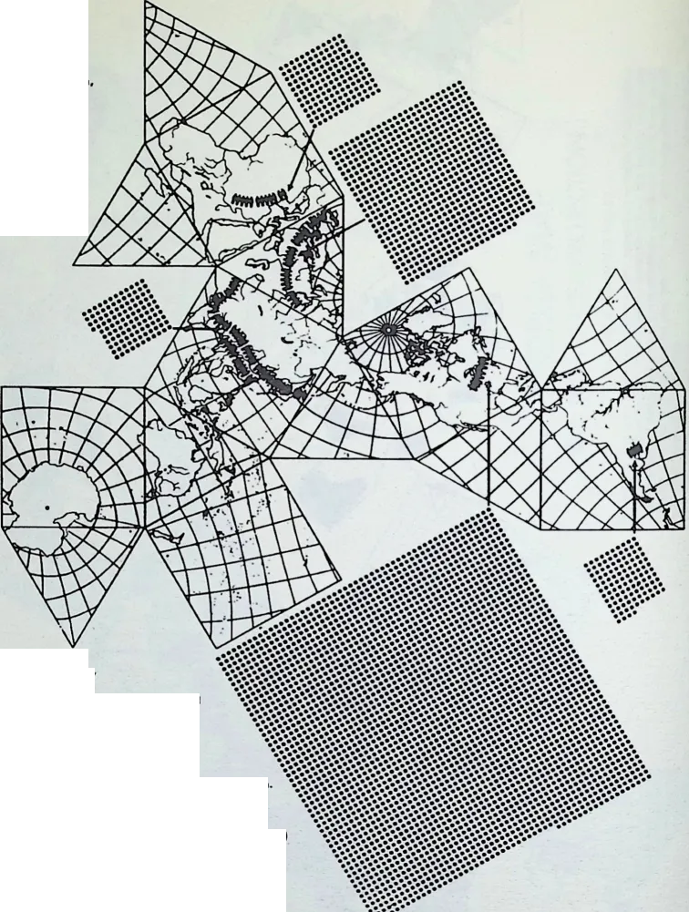 DYMAXION PROJECTION, patented 1946 by
343 R. Buckminster Fuller
344 Depicts spherical world as a flat surface with no visible distortion (only mathematically detectable). Poles need not be given symmetrical position because the longitude and latitude grid is developed after Its great circle grid prolection which may be freely oriented upon the globe’s sphere.
345 All openings In the stretched out earth ‘‘skin’’ occur In the one and continuous ocean. This allows the particular arrangement of linked together continental masses, without breaks In their contours, surrounded by ‘‘their’’ oceans 14 segments can be assembled In various combinations as three dimensional-approximation of a globe.
346 1% OF WORLD ANIMATE POPULATION
347348The curved arrangement of symbols indicates roughly the major population concentrations, see pps. 38-39.
349EACH DOT 1% OF WORLD HARNESSED ENERGY SLAVE POPULATION (inanimate power serving mao)
350 IN TERMS OF HUMAN EQUIVALENTS: Total 3800%
351 WORLD ENERGY MAP
352 by R. Buckminster Fuller
353 Short strands of red man symbols represent percentage of world population living In each region Black dots represent ‘‘energy slaves’’ serving these regions.
354 ‘‘Energy slaves’’ are determined as follows:
355 One man In one 8 hour day can do approximately 150,000 foot pounds of work (one foot pound = energy required to lift one pound one foot vertically).
356 1950 world consumption of energy from mineral fuels and waterpower (not including atomic fission) is estimated at 80-1/6 quintillion foot pounds. Assumed that man’s overall mechanical efficiency converts only 4% of consumed energy resources Into work, the not annual profit is 3-1/5 quintillion foot pounds.
357 Dividing this figure by 37-1/2 million foot pounds, one year’s (250 work days) energy output by machines and of one man, the result is 85-1/2 billion man year equivalents of work done structures. These equivalents we call ‘‘energy slaves’’ serving man.
358 85-1 ⁄ 2 billion energy slaves
359 2-1 ⁄ 4 billion world population =3S ,layp<r
360 Note
361 The atomic energy resource consumption during this period in various countries Is not available but would probably tend to Increase even further the present disparity of respective world energy advantages.
362 Also note that energy slaves are not confined to narrow range of physical conditions limiting man’s activities for they can work ‘‘comfortably’’ anywhere between absolute zero and 5,000°F., at submicroscopic precision and at speed of 186,000 miles per second.
363 % OF WORLD POPULATION 1950
364 ENERGY SLAVES % OF WORLD’S POPULATION ENERGY SLAVES
365ASIA 50
366EUROPE 24
367AFRICA AND MEDIT. WORLD 12
368NORTH AMERICA 8
369SOUTH AMERICA 4
370CENTRAL AMERICA 1
371ALL OTHERS 1
372 100%
3731950 1950
374. . . 2,565,000,000 3
375.’ . . 14,535,000,000 17
376. . . 3320,000,000 4
377. . . 62,415,000,000 73
378. . . 2,565,000,000 3
379 0 0 0 0 85,500,000,000 100%
380 PROPORTIONAL % OF WORLD’S ENERGY SLAVES in terms of A and human equivalents as shown on map 1950 114 646 152 2774 114 0 0 3800%
381 ENERGY SLAVES PER HUMANS PER AREA (In round numbers) 1950 2 27 13 347 28 0 0
- 250.
- The World Energy Map pictured on a Dymaxion Projection, first published by Fortune, February, 1940. The man symbols represent the percentage of world population in each region. The black dots represent the percentage of ”energy slaves’’ serving the regions.
NAME
OF MAP
PIECES | POPULATION | %
OF
WORLD
POPULATION
>940
1950 | ENERGY
SLAVES
POPULATION | % OF
WORLD’S
ENERGY
SLAVES | % OF
WORLD’S
ENERGY
SLAVES
In
Terms of
Human
Equivalent
As
Shown
On Map
1940
1950 | SLAVES
PER
HUMANS
PER
AREA
In
Round
Numbers
1940
1950
j | ||||
3821940 | 3831950 | 3841940 | 3851950 | 3861940 | 3871950 | |||||
388ASIA | 3891,062,500,000 | 390,125,000,000 | 39150 | 39250 | 3932,21 1,000,000 | 3942,565,000,000 | 3956 | 3963 | 397102 114 | 3982 2 |
399EUROPE | 400531,250,000 | 401540,00.0,000 | 40225 | 40324 | 4048,475,500,000 | 40514,535,000,000 | 40623 | 40717 | 408391 646 | 40916 27 |
410AFRICA AND MEDIT. WORLD | 411255,000,000 | 412270,000,000 | 41312 | 41412 | 4152,579,500,000 | 4163,420,000,000 | 4177 | 4184 | 419119 152 | 42010 13 |
421NORTH AMERICA | 422148,750,000 | 423180,000,000 | 4247 | 4258 | 42622,110,000,000 | 42762,415,000,000 | 42860 | 42973 | 4301020 2774 | 431148 347 |
432SOUTH AMERICA | 43385,000,000 | 43490,000,000 | 4354 | 4364 | 4371,474,000,000 | 4382,565,000,000 | 4394 | 4403 | 44168 114 | 44217 28 |
443CENTRAL 444AMERICA | 44521,250,000 | 44622,500,000 | 4471 | 4481 | 4490 | 4500 | 4510 | 4520 | 4530 0 | 4540 0 |
455ALL 456OTHERS | 45721,250,000 | 45822,500,000 | 4591 | 4601 | 4610 | 4620 | 4630 | 4640 | 4650 0 | 4660 0 |
4672,125,000,000 | 4682,250,000,000 | 469100% | 470100% | 47136,150,000,000 | 47285,500,000,000 | 473100% | 100%
1700%
3800% | |||
- 251.
- World Energy Chart.
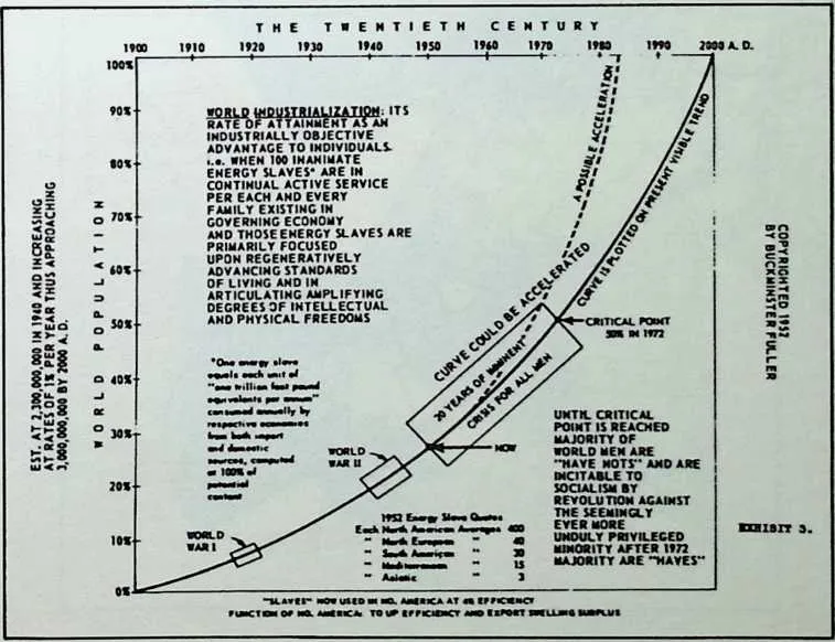
- 252.
- Graph showing the rate of attainment of world industrialization to 1952 and the projected rate to the year 2000.
475253 Fuller’s 1954 edition of the Air Ocean World Map eliminated the Arctic sinus (retained in the 1944 edition) and employed the icosahedronal triangular symmetry instead of that of the Vector Equilibrium.
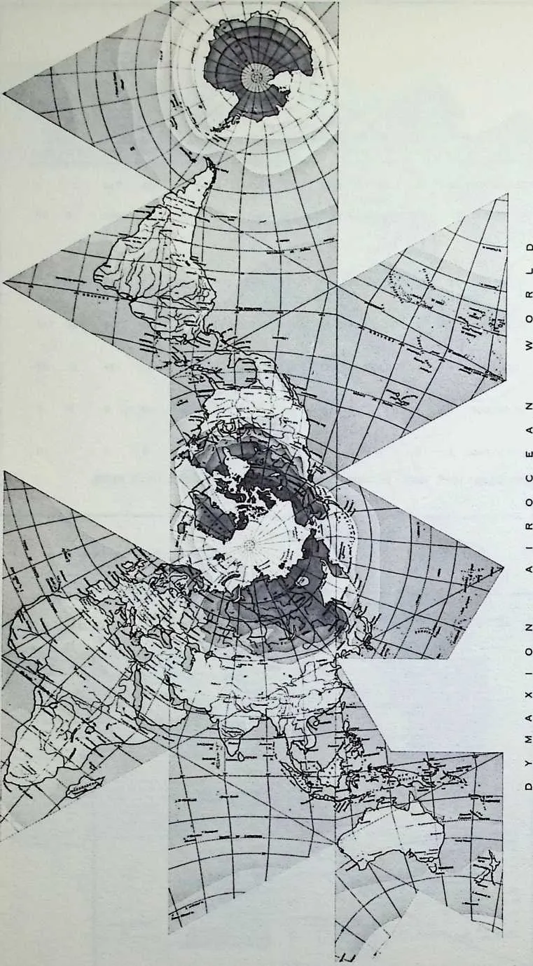
477254–255 Drawings showing method of Fuller’s topological cartographic transformation from spherical to planar surfaces.
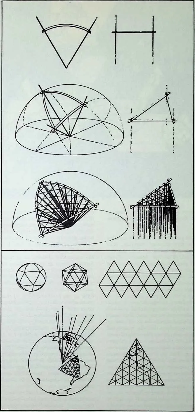
- 256.
- World arrangement of Dy maxion Map showing ‘‘World One —Water Ocean.’’ The original caption read as follows:
479This is the fundamental pattern of inherently divided lands, and their respective peoples’ energies, economics, mores, dreams and volitions. This pattern dominates all pre-World-War-One history. Water routes represented the shortest distances between the otherwise remote lands and peoples. Water routes represented the most economical lines of communication. Long distance communication consisted alone of written or face to face transmission—most swiftly completed by water.
480The tonnage commerce of inorganic and organic world resources could only be accomplished in water borne vessels. Only token commerce and slow messages could be accomplished via the backs of men or animals traveling the long way—via the plains and mountains around the headwaters. The divided peoples thought and spoke of their own uniquely predominant oceans as constituting separate oceans—Atlantic, Pacific, Indian. The great one Waterocean world pattern was unseen by world people. It was and is, in fact, one ocean with one central island—Antarctica—clockwise around which ever races west-to-eastward the winds and waters. This gigantic merry-go-round —called the ‘‘roaring forties’’ (entered into at 40 degrees south latitude)—is now known as the southern hemisphere’s jet stream area. Ships out of the Atlantic, Indian or Pacific Oceans were swiftly borne west-east by the merry-go-round to choose their re-entries into those oceans and their local lands. Whoever commanded the unsinkable ships (islands) commanding the mouths of the local bays, harbors, estuaries, channels and passages, and commanded the islands and capes which governed entrance upon the merry-go-round—then they governed the world. It is only now discernible by world peoples that centuries ago the masters of the unsinkable British Isles had discovered, held secret and commanded until World War One this Waterocean World. With only the unpeopled Antarctica at their back, and holding fortified bases at the southern extremities off South America, South Africa and Austral-Asia, they came from the south upon the ‘‘soft bellies’’ of the essentially northern hemisphere dwelling people. Only one-quarter of the earth’s surface is land; approximately 85% of the land and 85% of the people are situated north of the equator. The entire pattern of the world’s cities and their positionings grew out of the commerce and communication flows of the Waterocean World. Because the key to World One’s dominance lay in the water reaches invisibly remote from public sight and ken, the battles for its dominance were remote and often unknown to world peoples. Its masters were inherently invisible. The high priority technologies and resources were usurped by the invisible masters for their invisible struggles for Waterocean World dominance. This was a struggle not only of men against men, but also of men against the sea —its daily sea-quakes and avalanche-magnitude shock impacts, etc.
481The glories of technology and wealth went to the sea and much of it eventually to the sea’s bottom. The unwanted, inferior technologies and resources were left to ‘‘make do’’ with the inferior magnitude physical problems of the remotely pre-occupied struggling humanity upon their respective separate lands. The theoretical interlinkage of the peoples over the North
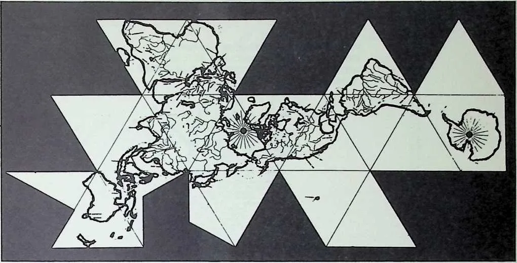
483Pole was utterly hidden in that approximately infinite direction of impenetrability. In the polar ‘‘infinity’’ lay the seemingly inherent insurance of the success of the grand strategy of the one invisible ocean world and its secretly known, most favorable dynamic routings. R. Buckminster Fuller, June, 1956.
- 257.
- Rearrangement of same Dymaxion Map showing ‘‘World Two —Air Ocean.” The original caption read as follows:
484This is the fundamental pattern of inherently integrated lands and their respective peoples’ energies, economics, mores, dreams and volitions. This pattern dominates all post-W orld-War-Two history. It centers about the North Pole, around which, counter-clockwise west-to-eastward, races the northern hemisphere’s jet stream at 200 to 400 miles per hour. 88% of the world’s people dwell in the Asia-Europe-Africa quadrangle on one side of the Pole. The remaining 12% dwell in the Americas on the other side of the Pole. Approximately all shortest routes between the people in North America to the 88% on the other side of the Pole lie over the Arctic. The Atlantic and Pacific Oceans on either side of North America are routes to nowhere. Shortest distance from North America to South America is over Central America and the West Indies—not over the Atlantic or Pacific.
485Voice to ear communication between all peoples anywhere around the world is approximately 186,000 miles per second. In terms of mores, languages, politics, they are as yet months, years and generations apart. In the terms of human needs and longings for understanding, they are as one.
486In the swiftly accelerating range and frequency of world peoples? comings and goings, the inherent barriers of mores, politics and languages will swiftly dwindle and disappear. All of the pattern of world affairs will become visible to all its people. Ambitions of individuals or of minorities to seize dominance of the Airocean World are inherently visible ”spot news.’’ Democratic mastery of the whole pattern by all the people is inherent and inevitable. The intellectual and technological integration accelerates the constant trend to serve more needs of more people with higher standards with ever more efficient investment of overall resources per given function. This process of doing more with less may be capsuled as ‘‘ephemeraliza-tion.’’ The more ephemeralization advances the more flyable becomes any one cargo. The trend of the Airocean World is toward an entirely airborne technology. Cities and towns will tend to become Airocean bottom cloverleafs integrating highways and airways. The highways and airways will become a unitary world network. Sea and waterport cities will trend to diminishing cargo interchange significance and increasing recreational and abstract process significance.
487 1250 A D 1290 1330 1370 1410 1450
488 i6o
489 1490
490 1570 1610 ibb0


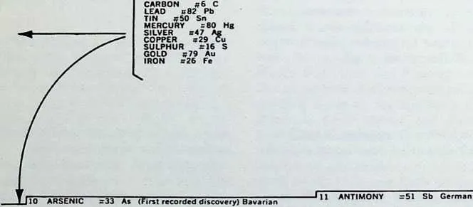

493 9 ELEMENTS were acquired by civilization prior to historic record of the events, probably in Asia millenniums ago.
494 8
495496EARTH ORBIT IN MAN MADE ENVIRONMENT CONTROL: PRODUCT OF SUCCESSFUL APPLICATION OF HIGH PERFORM ANCE PER UNIT OF INVESTED RESOURCES
497PROFILE OF THE INDUSTRIAL REVOLUTION AS
498EXPOSED BY THE CHRONOLOGICAL RATE OF
499ACQUISITION OF THE BASIC INVENTORY OF COSMIC ABSOLUTES-THE 92 ELEMENTS

501 APPROXIMATE CUMULATIVE
502 >50
503 1250 A.D 1290 1330 1370 1410 1450 1490 1530 1570 1610 1650
- 258.
- Dymaxion profile of Industrial Revolution, first presented by Fuller in 1943, at a meeting of the Chalkley Thursday Science Luncheon Club, a group of leading U. S. and English scientists who met weekly at the Cosmos Club, Washington, D.C., during World War II. This is the curve of initial acceleration of pure science events. Fuller holds that pure science paces applied science, applied science paces technology, technology paces industry, industry paces economics, and economics paces the social, political, everyday catch-up. Fuller maintains that this curve is reliable as a fundamental shape of world history’s evolutionary speed-up, because it consists of a controlled family or set of events. It is the finite set of all isolations by man of all the ”regenerative’’ chemical elements up to and including uranium. The trans-uraniums are non-regenerative. All the regenerative elements replace their pattern in nature:
504 1970
505 ROCKET
506 STEAMSHIP
507 atomics commence.
508 93 92’ 91
509 90 FRANCIUM
510 2010 A D
511 88
512 = 86 Rn Gr.
513 82
514 81
515 80
516 AIRPLANE
517 103 LAWRENCIUM =103 Lw USA
518 102 NOBELIUM =102 No Eng . Swed .USA
519 101 MENDELEVIUM =101 Md USA
520 100 FERMIUM
521 99 EINSTEINIUM CALIFORNIUM BERKELIUM PROMETHIUM
522 96’
523 95 AMERICIUM
524 CURIUM -PLUTONIUM NEPTUNIUM ASTATINE
525iioo Frn MA*.
526 -99 Es USA
527 -98 of USA-
528 =97 B‘ ?,s*
529S61 Pm U.S.A. ciaims to 19K
530 = 95 Am U.S.A
531 = 94 Pu USA
532 = 93 Np U S.A 85 At U.S A
533 19 TECHNETIUM =43 Tc USA.
_ RHENIUM =75 Re Gr
HAFNIUM =72 Hf Netherlands. Hung
PROTACTINIUM =91 Pa Gr . Aust.
53453585 LUTETIUM =71 Lu Fr I RADON ----
536ACTINIUM
537POLONIUM ..
538RADIUM =88 Ra Fr. XEON =54 Xe Scot.. Eng. KRYPTON =36 Kr Scot. Eng. NEON =10 Ne Scot . Eng EUROPIUM—--
539HELIUM ARGON = GERMANIUM DYSPROSIUM NEODYMIUM PRASEODYMIUM GADOLINIUM = SAMARIUM HOLMIUM SCANDIUM THULIUM YTTERBIUM GALLIUM INDIUM THALLIUM RUBIDIUM CESIUM UTHENIUM 58 ERBIUM 57 TERBIUM 6 LANTHANIUM VANADIUM 4 THORIUM 1 BROMINE ALUMINUM SILICON SELENIUM 49 CADMIUM 48 LITHIUM t IODINE BORON BARIUM STRONTIUM CALCIUM POTASSIUM SODIUM ; MAGNESIUM IRIDIUM OSMIUM PALLADIUM RHODIUM CERIUM i TANTALUM . COLUMBIUM CHROMIUM BERYLLIUM YTTRIUM 29 TITANIUM 28 ZIRCONIUM 27 URANIUM 26 TUNGSTEN 25 TELLURIUM >4 MOLYBDENUM MANGANESE CHLORINE OXYGEN = NITROGEN FLUORINE HYDROGEN ..
540 NICKEL =28 Nc Swedish
BISMUTH =83 Bi French
5 ZINC ~
541 _ PLATINUM 13 COBALT 12 PHOSPHORUS #15 P German
542 65
543 55
544 NOTE:
545 63
546 62
547 61
548 70
549 69
550 23
551 22
552 21
553 20
554 = 30 Zn German = 78 Pt Spanish
555 21 Co Swedish
556 40
39
38
37
36
35
557558=2 He Scottish 18 A Eng-Scot =32 Ge German = 66 Dy French = 60 Nd Austrian = 59 Pr Austrian ;64 Gd Swiss = 62 Sm French = 67 Ho Swedish =21 Sc Swedish = 69 Tm Swedish =70 Yb Swiss =31 Ga French = 49 In German = 81 Tl British = 37 Rb German ^55 Cs German =44 Ru Russian =68 Er Swedish = 65 Tb Swedish = 57 La Swedish :23 V Swedish = 90 Th Swedish =35 Br French #13 Al Danish = 14 SI Swedish = 34 Se Swedish = 48 Od German 3 Li Swedish
559 = 53 I French
560 = 5 B French
561 = 56 Ba English *1 =38 Sr English
562 =20 Ca English = 19 K English Til Na English = 12 Mg English 77 Ir English 76 Os English =46 Rd English =45 Rh English 58 Ce Swedish =73 Ta Swedish = 41 Cb English = 24 Cr French =4 Be French :39 Y Finnish :22 Ti English
563564=92 U German 74 W Spanish r52 Te Austrian =42 Mo Swedish = 12 Mg Swedish
565 —17 Cl Swedish
566 8 O English
567 = 7 N Scottish = 9 F Swedish = 1 H English
568 Radioactive. No stable isotopes
569 NUMBER BEFORE NAME OF ELEMENT INDICATES ORDER OF DISCOVERY. NUMBER FOLLOWING NAME IS THE ATOMIC NUMBER LETTERS FOLLOWING ATOMIC NUMBER ARE THEIR SYMBOLS NATIONALITY LISTING IS THAT OF DISCOVERER.
570 TOTAL OF KEY INVENTIONS OF SCIENCE AND TECHNOLOGY
571 450
572 1.450 10.000
573 1690
574 1730
575 1770
576 1810
577 1850
578 1890
579 1930
580 1970
581 2010 A.D
582 Copyright 1946 and 1964 by R BUCKMINSTER FULLER
583”Unlike an open-ended set of scientific events selected for the individual excitement but having no inherent beginning or end whose chronological patterning has therefore no clearly readable significance, this set of the first regenerative 92 chemical elements which—as far as man knows
584has been present in nature forever, and its arrangement chronologically by the dates of the respective isolations by man, represents a true, finite, complete set predicated upon the mathematical regularity of their electron-proton counts from I to 92. The visibly quickening chronologicality has therefore valid significance. This radially accelerated curve may have been caused by factors as yet undiscovered. But in itself, its consistent acceleration takes place without man’s consciousness of its shaping.”
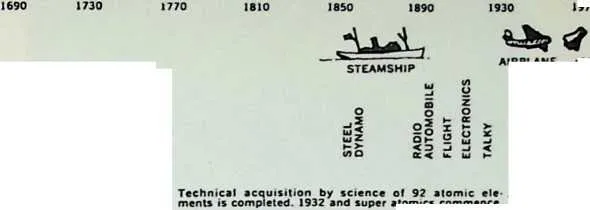
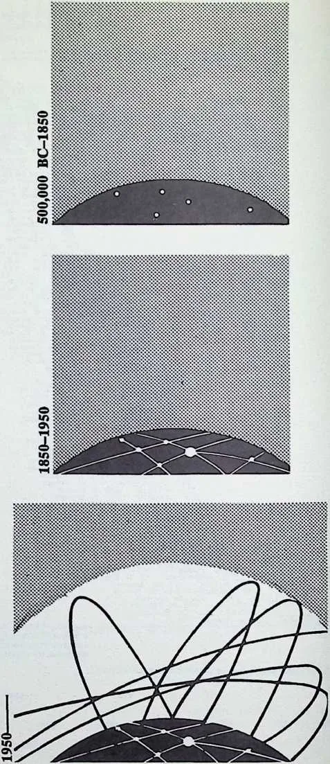
- 259.
- Ecological geometry of Man on Earth. The original caption read as follows:
587588Shown here are the three most distinct pictures of the history of man’s years on earth. Picture one may be called. ”The first half million years were the hardest.” Ignorant and isolated, man was unaware of other men and of the potentials of friendship, integrated resources, and mutual survival. The first picture is of a micro-bespeckled, enormous sphere, an arithmetical isolation, a physical impasse, escapable only through intellect, instrumented—through science.
589Picture two shows man linking up resource and survival by lines of transport and communication. Wealth is generated astronomically. Standards go up. Health and life expectancy tend to double. But in 5000 years the velocity of integration and increased energy flow leads to an arterial cloggage and explosive high pressure. The two-dimensional picture is a neat linear equation, fulfilled—and again occurs an impasse escapable only by intellect.
590Picture three shows the intellectual answer—a new volumetric and dynamic dimension—wireless, trackless, omnidirectional. It is a high-frequency interaction of time synchronized, relaying from resource to logically dispersed processing centers for physical separation, reintegration, and unimpeded direct flow to next function. It bypasses all constrictions, yet in every way facilitates man’s range and frequency of voluntary assembly and separation in a continuity of ever higher standards of environment and process control. Picture three is a moving picture. Everywhere its physical facilities move with ever-increasing velocity and synchronized knowledge, allowing man to choose when and how and where he wishes to move. He specifically controls his own accelerations and decelerations. Picture three’s scientific key is: to serve an ever-increasing number of functions of more people more of the time, with an ever-decreasing investment of energy, matter, and numbers of parts per unit of function, by ever greater intellectual re-investment of man’s unique capital asset, ”hours of time of his life.”
591Picture one is very long, as it was ”against forces.” Picture two is very short, as it was ”transitional.’’ Picture three will again be very long, as it is truly ”natural.” It synchronizes with the dynamic universe. The evolution of its ”transport species” is multiplying. Here we go .. . but you need not hold your hat . . . it won’t blow off. Buckminster Fuller, 1950.
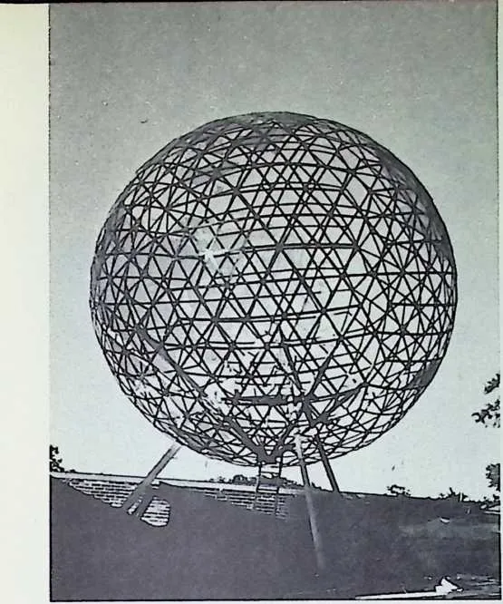
- 260.
- Miniature Earth, 20 feet in diameter, installed by Fuller and Cornell University students on roof of university building in Ithaca, New York, May, 1952. The patterns of the continents were developed by bronze fly screen overlays. The North-South pole axis, when installed, paralleled the axis of the earth. When the observer sighted through the South Pole, the North Pole lay neatly on Polaris (in the actual sky). Ithaca was in zenith. The center of the Miniature Earth was only 4,000 miles from the center of the actual earth. The star nearest to the earth (the sun) is some 92,000,000 miles away. The displacement between the real earth’s and the Miniature Earth’s centers was observationally negligible. With the eye of observer at center of the Miniature Earth, the view through the dimly outlined continental screens, was not measurably different from the ”view” from the center of the real earth through a transparent crust of the real earth. From this position, all the real stars in the heavens, seen by a Cornell Miniature Earth central observer, appeared in true zenith over points around the Miniature Earth, exactly as they appeared over points around the real earth. A star seen in zenith outward of London, England, Miniature Earth, was actually at zenith over the British Isles. The Cornell Miniature Earth was a psychologically effective planetarium. ”From its center,’’ Fuller said, ”you began to see, and feel, the earth to be revolving in the presence of the stars, in contrast to the everyday mis-sensing of this phenomenon.’’
593Fuller, in 1955, developed, with University of Minnesota students, the mathematical calculations for a 400-foot-diameter Miniature Earth, to be mounted on Blackwell’s Ledge, in New York City’s East River. This project, if completed, would confront the United Nations’ Building with a Miniature Earth so large that on it individual, proportionally scaled houses around the earth could be directly visible.
594The industrial revolution’s railroads and trucks were the beginning of the disappearance of the age-long dominance of the water borne traffic. Railroads and trucks represented shiploads ”sailing’’ over a new Landocean. With man’s penetration to the North Pole, discovery of wireless communication and invention of trackless, omni-directional, heavier-than-air air flights at the beginning of the Twentieth Century, the swift obsolescence of World One’s Waterocean was certified. World War One and World War Two and their twenty-two-year interim represent the transitional period from a predominantly Waterocean World to an Airocean World.
595All the pain of this fundamental historic transition is inherent in the momentum of ignorance of man in general concerning the inexorableness of the fundamental reorientation of his life experience. The operational principles of physical universe persist throughout man’s approximately ignorant endurance of the transition. But as men learn more of the persistent verities and integrities of universe, they discover the fundamental necessity of reorientation of knowledge in respect to those verities.
596Einstein’s Relativity, born at Twentieth Century’s opening, and its security in comprehended dynamic equilibrium becomes the newly acquired norm of the Airocean World, replacing the no longer tenable static norm of ”at rest’’ and ”death’’ and its invalidated securities of mass and inertia.
597Lincoln’s industrially catalyzed awareness that ”right” had come to ascendency over ”might’’ is of the essence despite all ignorantly detoured chaos of transition. There are no invisible masters of World Two. Visible masters are anathema in World Two. World Two is inherently governable only by the complementary integrities of initiative of the individuals of democracy. By R. Buckminster Fuller, June, 1956.
TENSEGRITY
598261 Fuller and his first 1927 Tensegrity structure, a mast and double wire-wheel system as seen through the keyhole of a Greenwich Village studio, 1929.
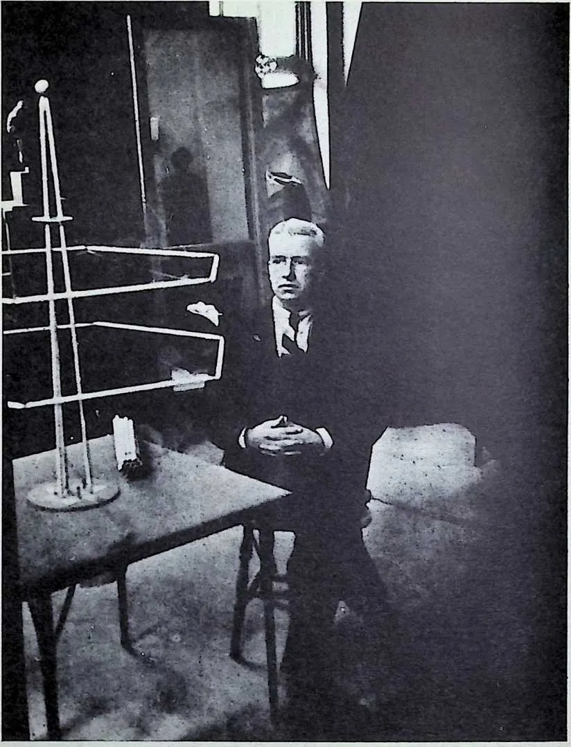
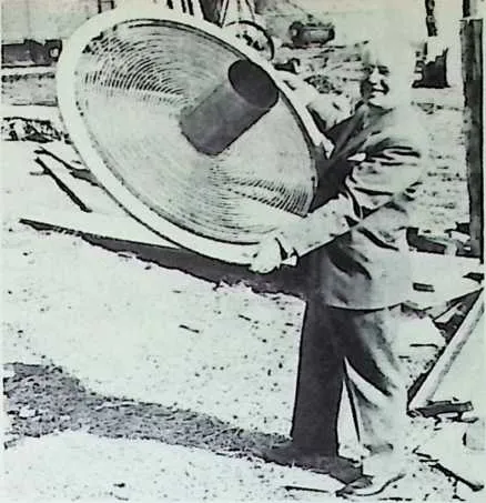
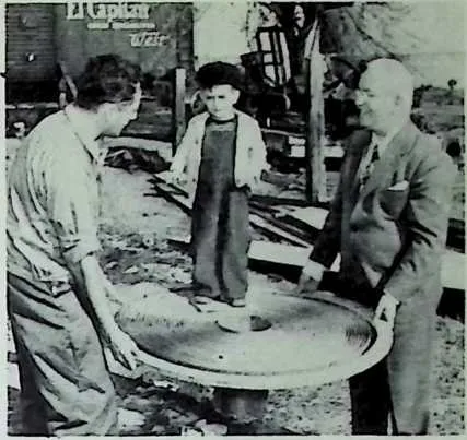
601262-263 Fuller, with an experimental Tensegrity structure, Wichita, Kansas, 1944-
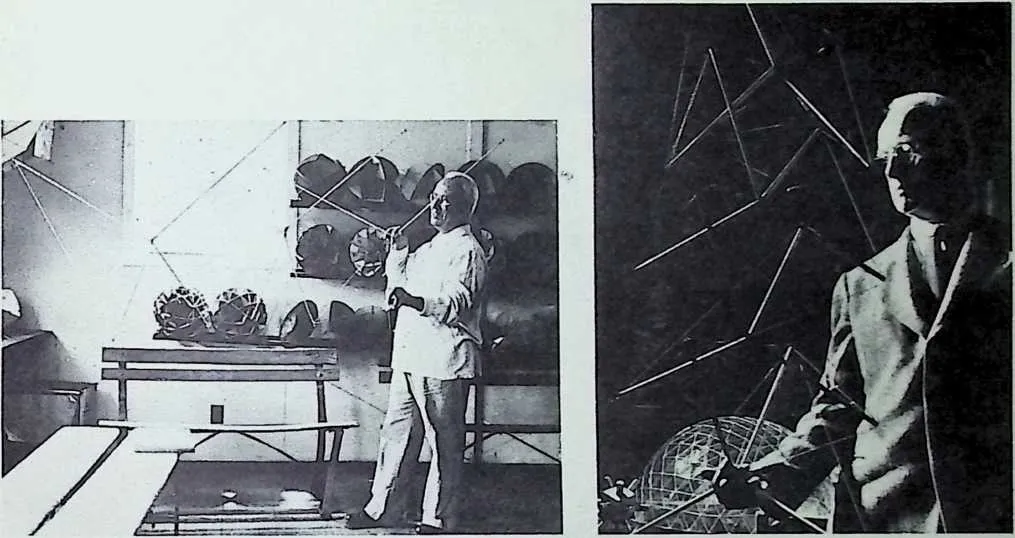
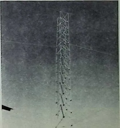
- 264.
- Fuller’s first Tensegrity Mast, Black Mountain, North Carolina, 1949.
- 265.
- Fuller with Tensegrity Mast made by Kenneth Snelson, 1949.
- 266.
- Tensegrity Mast, North Carolina State College, 1950.
604 nf Oregon Tensegrity Mast, 1953-
605267 University of Oreg
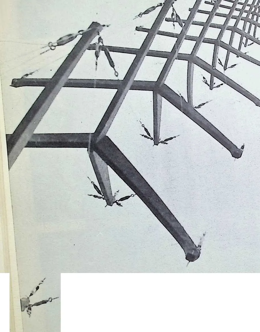
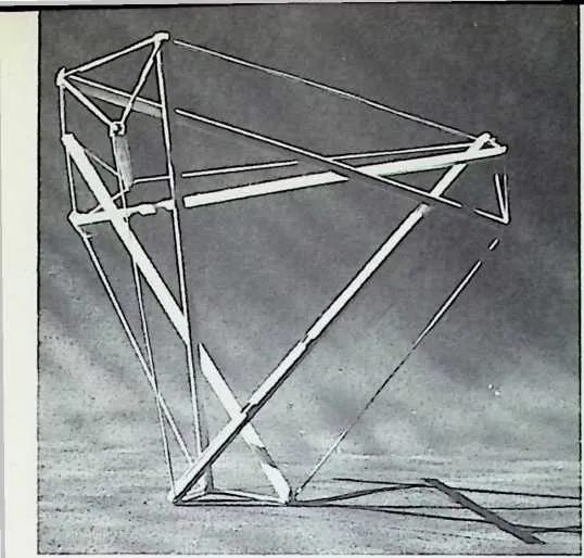
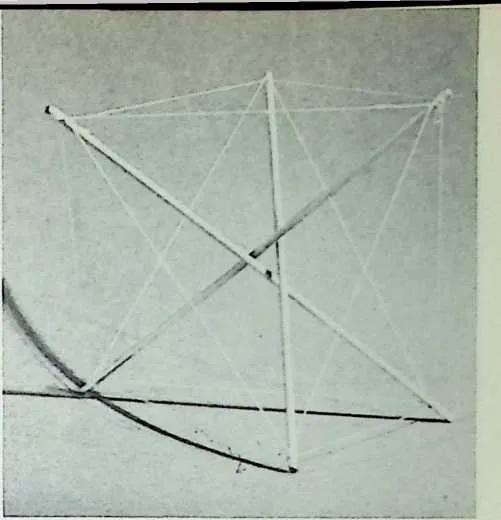
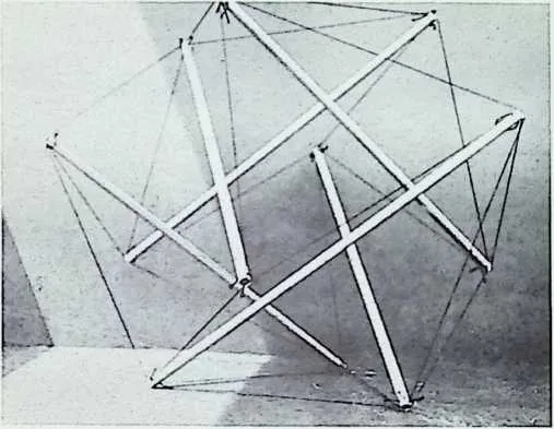
- 268.
- Tensegrity tetrahedron, developed by Fuller’s associate, Francesco della Sala, University of Michigan, 1952.
- 269.
- Tensegrity octahedron, developed by Fuller’s associate, Ted Pope, Toronto, 1957.
- 270.
- Tensegrity icosahedron developed by Fuller, Black Mountain College, 1949.
- 271.
- Tensegrity Vector Equilibrium, developed by John Moelman, North Carolina State University, 1951-
- 272.
- Tensegrity tricontahedron (30-sided figure), developed by Lee Hogden, North Carolina State College, 1953.
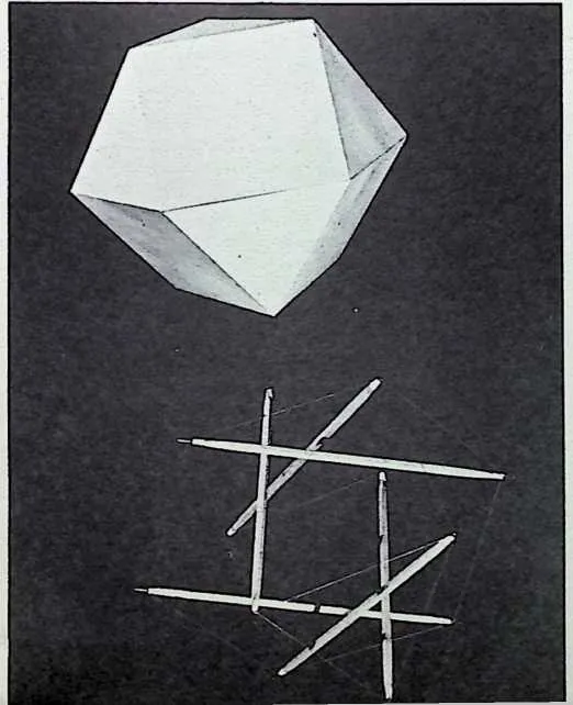
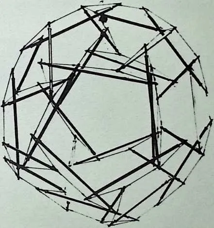
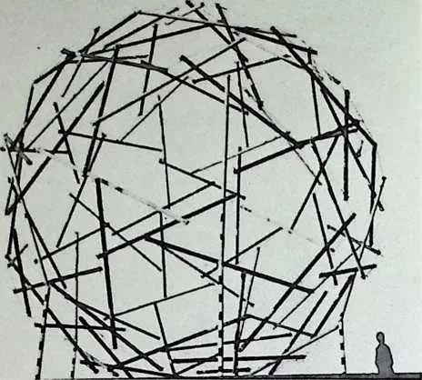
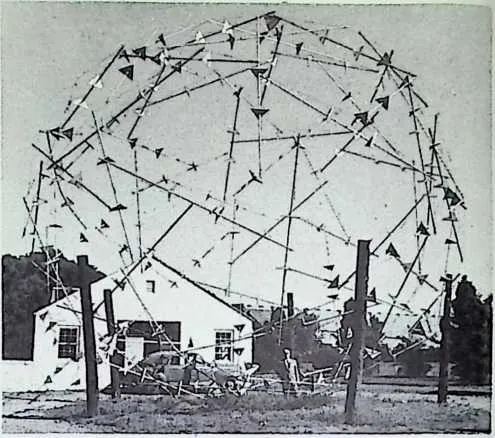
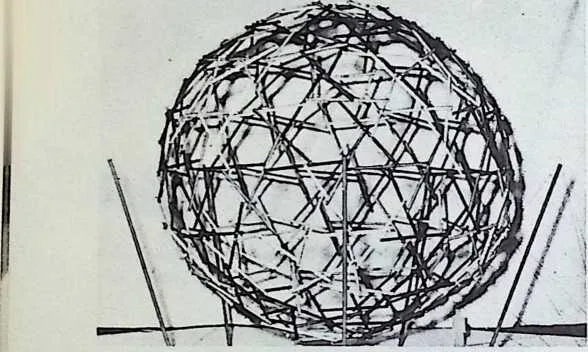
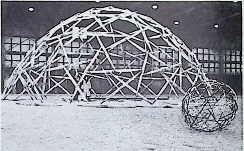

- 273.
- Ninety-strut Tensegrity enenticontahedron (90-sided figure), Princeton University, 1953.
612I
- 275.
- Ekatonogdoicontahedron, 270-strut Tensegrity, University of Minnesota, 1953.
- 274.
- Forty-foot-diameter, 90-strut Tensegrity, Princeton, 1953.
- 276.
- Forty-foot-diameter, 270-strut Tensegrity hemisphere, University of Minnesota, 1953.
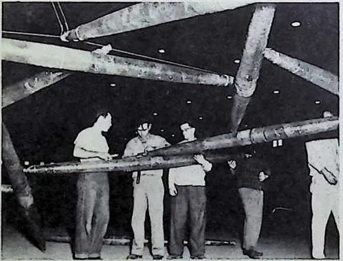
- 277.
- Closeup of University of Minnesota, 40-foot-diameter Tensegrity, during assembly, showing the discontinuous compression, continuous tension nature of the structure. The struts were 9 feet long, 6 inches in diameter, weighing 6 pounds each, and were fabricated of polyester-fiberglass. Each strut was capable of supporting a l-ton load when used as a column. If completed, the total weight of this 40-foot Tensegrity would be so small that the buoyancy developed in the hollow struts would be sufficient to float the structure in air. It would have the lift of a balloon despite the fact that the sphere itself was ”full of holes.’’
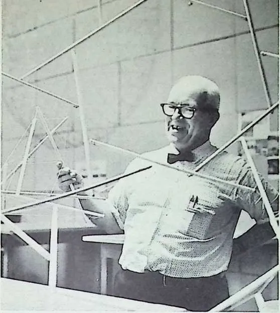
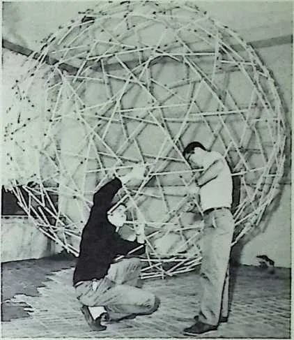
615278 Fuller with Tensegrity complex, at Southern Illinois University, 1958. In his right hand is a Tensegrity tetrahedron with interior tensional octahedron in which the struts lead between interior and exterior tensional system, providing a rigid truss.
616279 University of Oregon students, 1959, with 270-strut Tensegrity, in which every component is identical. In this system, Fuller has broken through to spheroidal systems of unitary modular denominators in frequency magnitudes of infinite series. (Each of the earlier Tensegrity systems required components of several modular dimensions.)
617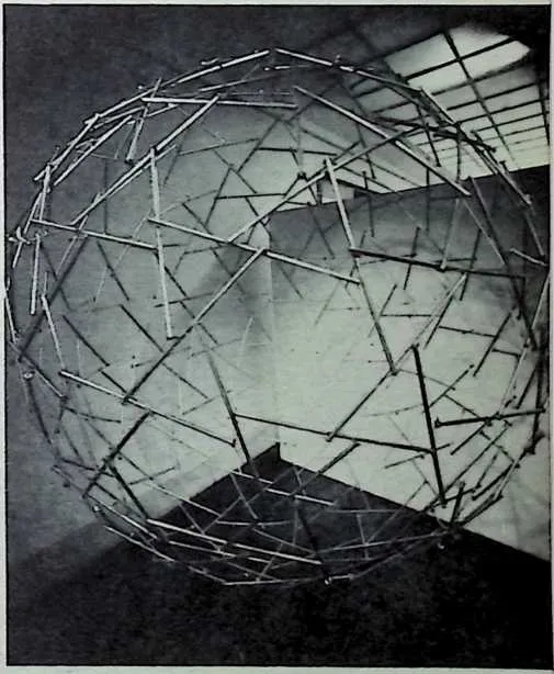 280 Unitary component Tensegrity hemisphere of 75 S.T. aluminum alloy
struts and Monel wires, Metropolitan Museum of Art, New York, 1959. Fuller
has calculated the load factors in Tensegrity structures of up to 2 miles in
diameter, and found such structures practical for present day aircraft industry
fabrication. These hemispheres could be assembled in large segments on the
ground, the segments then being flown into position by helicopter. A fleet of
16 of the large Sikorsky helicopters could fly all the pieces into position
in a mile-high, 2-mile-wide dome, in three months. A dome of this size
would cover New York City, east and west, from the East River to the
Hudson, at 42nd Street, and north and south, from 62nd Street to 22nd
Street—an area which includes all of the upper Manhattan skyscraper city of
1959. A dome of this kind would prevent snow and rain from falling on the
protected area. Since all the New York Steam Company and Edison Company
plants which supply this area are outside the circle, the dome would exclude
the primary fumes which now pollute the area. Only electrically-powered
motor vehicles would be permitted to operate under the dome; thus the
fumes now generated by gasoline and diesel cars, trucks and buses would be
eliminated.
OCTET TRUSS
618281 A section of the aluminum dome over the Ford Rotunda building showing the triangular grid Octet Truss system. (1953)
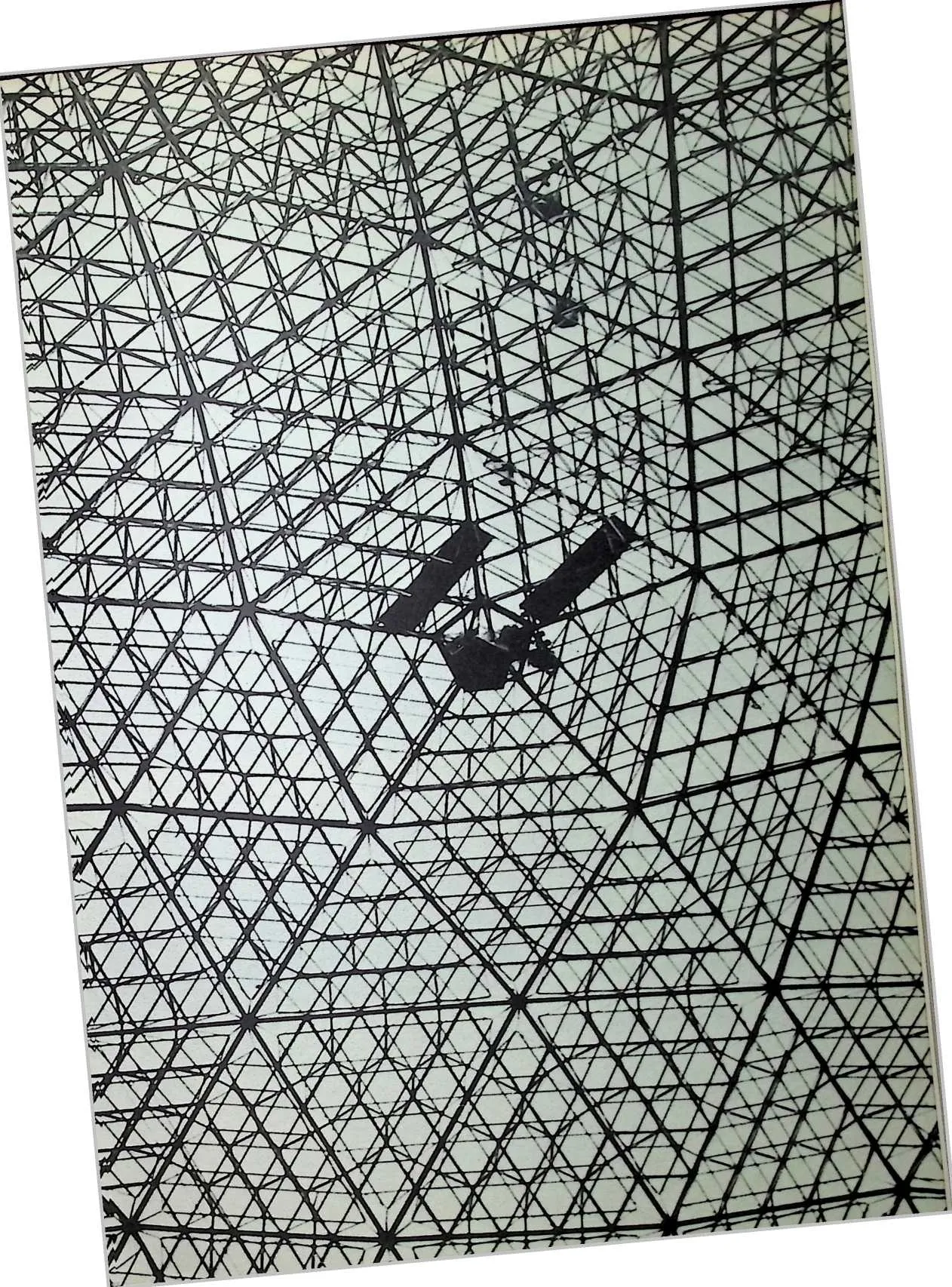
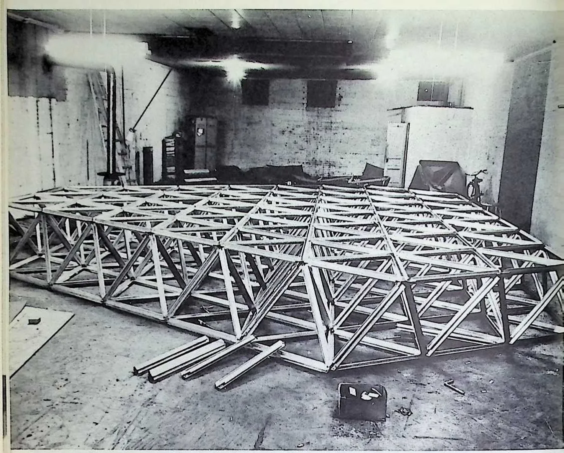
621282 Octahedron-tetrahedron (‘‘Octet’’) truss consisting entirely of struts. No hubs are required. X-shaped terminals of struts unite in such a manner as to weave around the hub nuclei, forming the four planes of the Vector Equilibrium. The truss has phenomenal three-way ‘‘finite” strength. In conventional beam structure systems, the supporting units are parallel to one another; their ends are infinite (that is, do not curve back into the system), and therefore do not help one another. In Fuller’s three-way-grid Octet Truss system, loads applied to any one point are distributed radially outward in six directions, and are immediately frustrated by the finite hexagonal circles entirely enclosing the six-way-distributed load. Each circle distributes the load 18 ways to the next circle, which ‘‘finitely” inhibits the radially distributed load. Thus the system joins together ”synergetically’’ to distribute and inhibit the loads. The total loads are finally distributed three ways to the three point support. An Octet Truss, loo feet long, 35 feet wide, and 4 feet deep, by Fuller, was exhibited by the Museum of Modern Art in September, 1959, along with one of his Geodesic Radomes, and a Tensegrity mast.
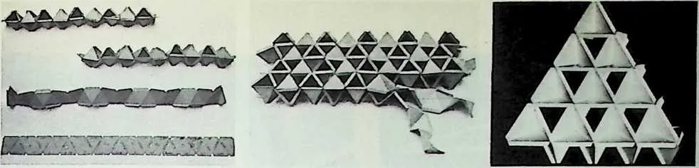
623283-285 The Octet Truss can be fashioned from flat ribbons by spot welding or other high speed cohering processes.
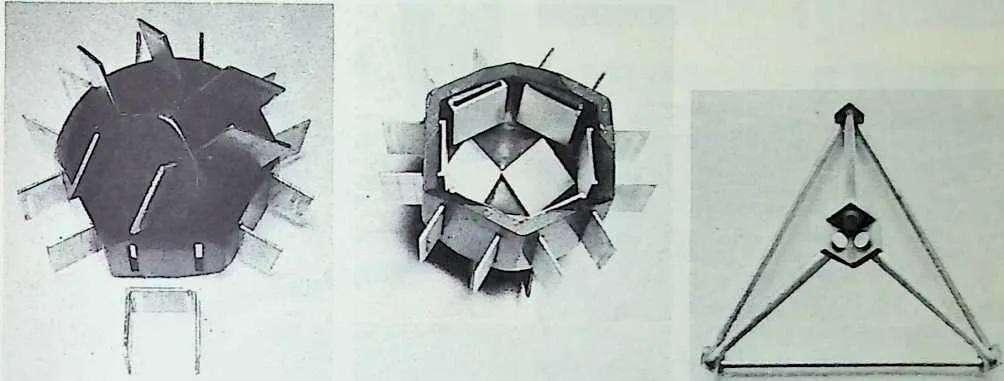
625286–287 The Octet Truss can be fashioned from hubs enploying the 12 faces of the rhombic dodecahedron. These two pictures show inside and outside of 12-way clevis cluster which holds the ends of struts.
626288 The Octet Truss can be assembled of tubes and rhombic dodecahedron hubs having face-mounted studs to slip into and fasten to tubes.
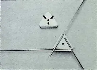
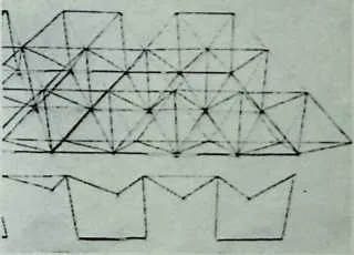
628289–290 The Octet Truss can be woven together with continuous rods and wires, seized together by male and female turbining hubs.
629291 The Octet Truss can be woven continuously from wire-like fencing structures.
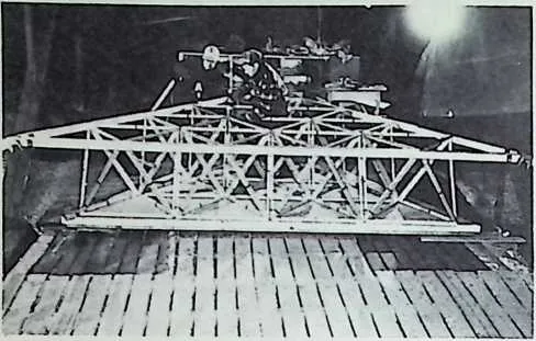
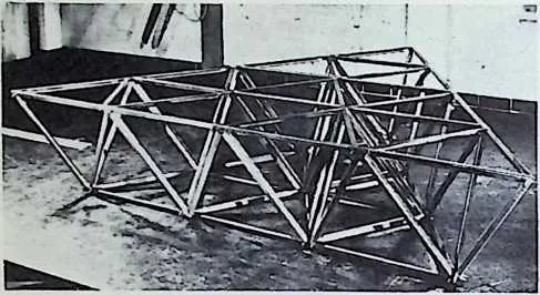
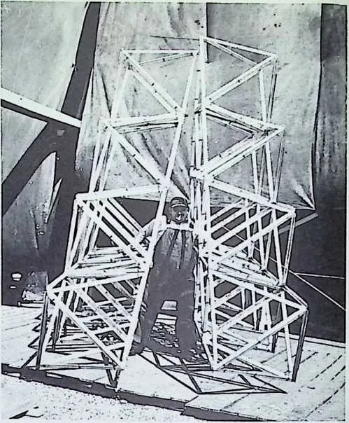
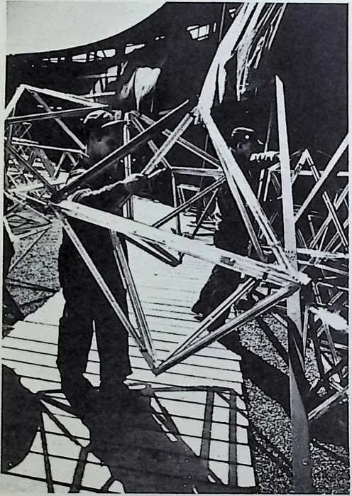
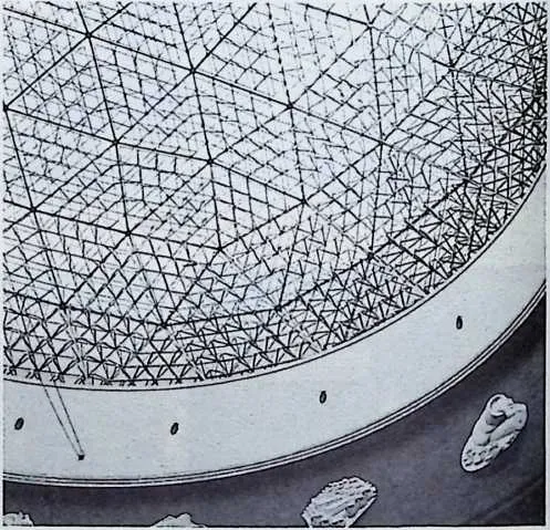
632292–297 Four-pound octahedra associated in Octet Truss complex were joined together to form the Ford Motor Company’s 93-foot-diameter Rotunda dome, weighing a total of 8V2 tons.
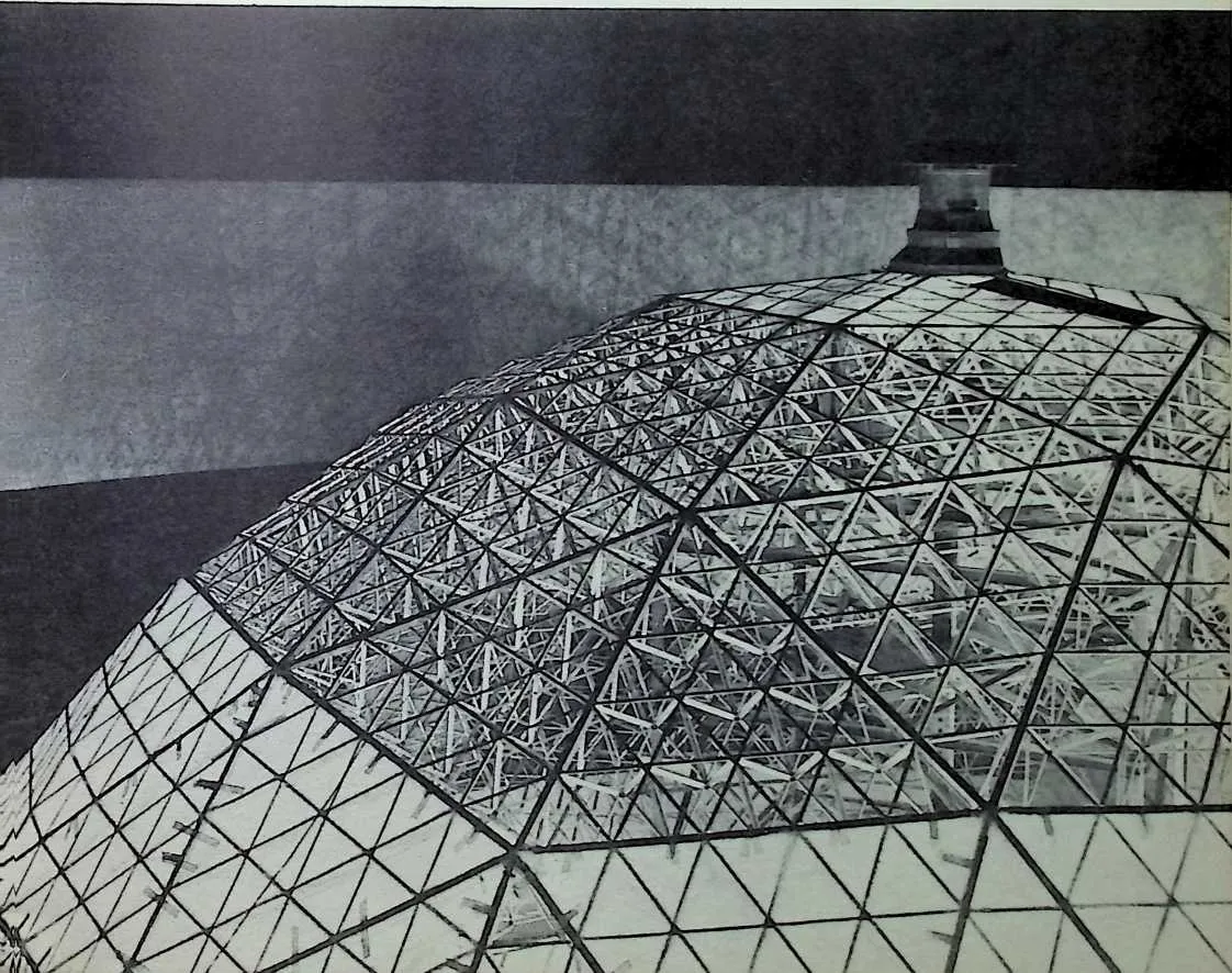
MINOR INVENTIONS
- 298.
- Tubular catamaran rowing shell invented by Fuller in 1947. The shell’s tubular bow and stern ends were demountable, as were the old-fashioned socket-assembled fishing rods. The craft’s over-all length was 22 feet; when sectioned in three fractions, it could be readily mounted on a car top ski rack. The width could be adjusted for slimness and speed. Light plastic nacelle contained the seat slide and foot tie-downs. Capsized oarsmen tumbled from single shells, cannot re-board and bail out. The catamaran rowing shell, by contrast, provided parallel-bar stability; thej-ower could easily remount between the bars.
634 PYM AX ION TUBULAR ROWING SHELL OF AIRCRAFT ALUMINUM , STEEL ,
PLASTIC. PORTABLE. SOCKET ASSEMBLY. SWEAT PROPULSION
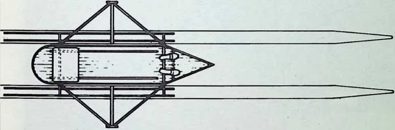
636 DIMENSIONS AND DISPLACEMENT DIAMETER OF TUBES.* 6’. O.A LENGTH:
22-0’ PNEUMATIC VOLUME i B.CUFT. A2.3B LBS-CU.FT)’ 500 LBS. DISPLACEMENT AT
WATERLINE (7* DlAMj 250 WEIGHT OF SMELL 50 LBS
637 SAFE WT. OARS 4 MAN 200 LBS.
638patent applied por
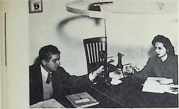
- 299.
- Fuller installed an overhead-trolleyed, tension-ally supported telephone in Wichita when war restrictions permitted only one telephone for an entire project. Fuller’s Wichita associates, Herman Wolf and Cynthia Lacey, are shown passing the phone.
- 300.
- Criss-cross, tensionally supported tables employed by Fuller in the Beech Aircraft Dy maxion Dwelling Machine project, Wichita, Kansas, 1944-45. These tables were first demonstrated by Fuller in the 1928 4D house.
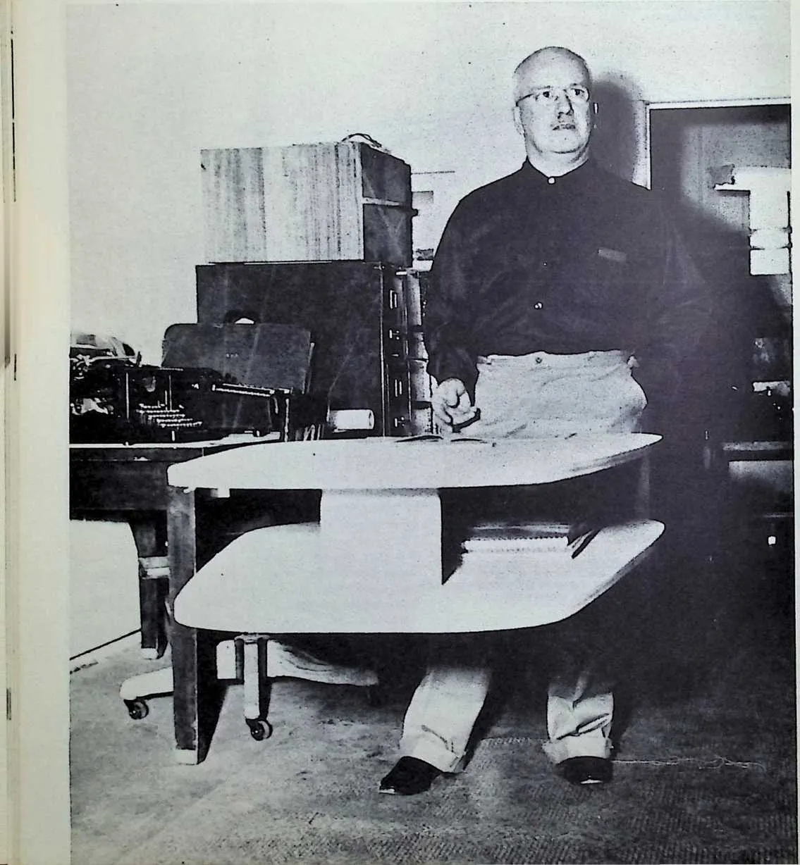
641 SECTIONAL B £ W
642’’IO V t J E AT’’
643< H 7 C M E 8 I I £ L J il 5 I S UATERVROOIEV BlttfU
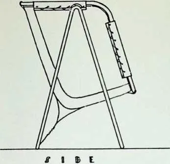
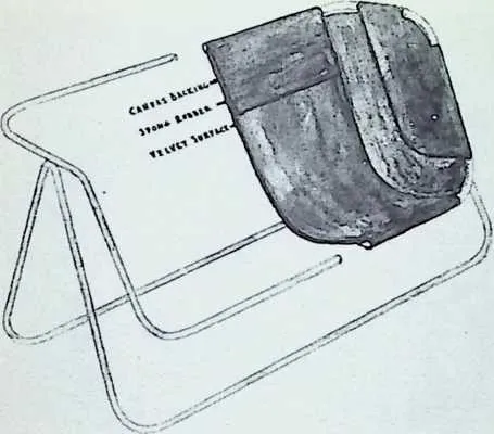
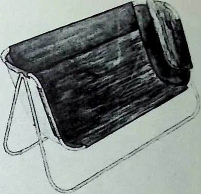
6456468 MUNICH H HUlI. DLJUNlt
647Sil Lt r=. !’-o” tt-30-3 1 M.t
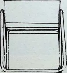
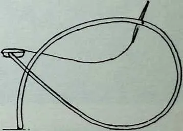
649301–302 Love seat and spring seat designed by Fuller in 1931. Both are tensionally seated.
650 i8o
651 AUTONOMOUS PACKAGE
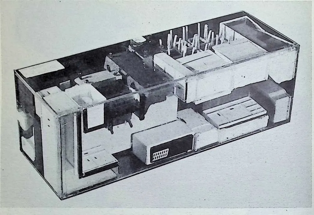
653654303–307 Model of 25-foot long, 8-foot high, 8-foot wide, legally-permitted road trailer package, developed by Fuller’s students at Chicago’s old Dearborn Street Institute of Design in 1948. The unit was formed by six panels which were hinge-mounted together. Each of the four 8 X 25 foot panels, and each of the two 8 X 8 foot panels functioned as a chassis for furniture and utilities. Various items were to be attached as they progressed down the line. A complete inventory of furniture and household apparatus for a family of six, including luxury accessories, could be so grouped and fastened to the six panels that when the panels were hinged out in a T-shaped pattern, they provided the facilities of a bedroom, living room, kitchen, and two baths, with all utilities manifolded and electrically harnessed together, ready for use. The total working and living area was 928 square feet of floor space. U. S. guaranteed mortgage standards permit first class five-room dwelling loans to 1000 square foot units. The students found an
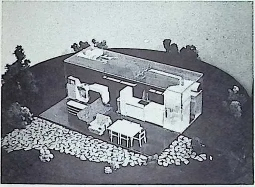
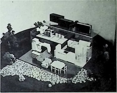
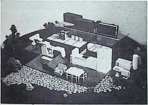
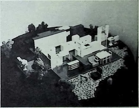
656arrangement of these temporarily fastened components on the panels which would permit the panels to be hinged together to form the trailer box package. The items that jutted out from any one panel were positioned to register with spaces in the other panels. This rigid alignment of shipped components—called ”jig shipping’’—had been developed for the motor deliveries of delicate aircraft parts in World War II. The ‘‘Autonomous Package” experiment was not significant in its superficial results. However, it proved that mass assembly and delivery of complete household high standard equipment was possible and economically feasible. Consequences of such mass fabrication, purchase, assembly, and distribution would reduce radically the over-all costs and weights of individual shipping containers. It was found that a family of six could have all the sanitary, metabolic, hobby, and self-development facilities on chattel mortgage terms, for a total of $1500. The same package, with items separately acquired, would cost $18,000.
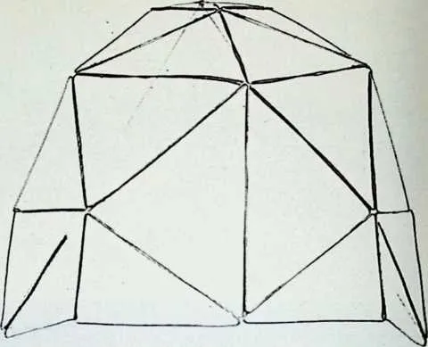
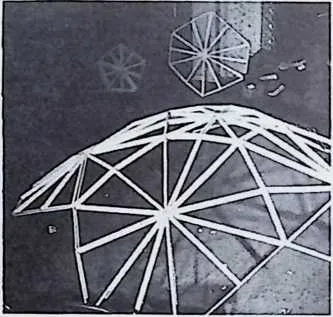
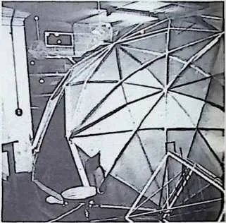
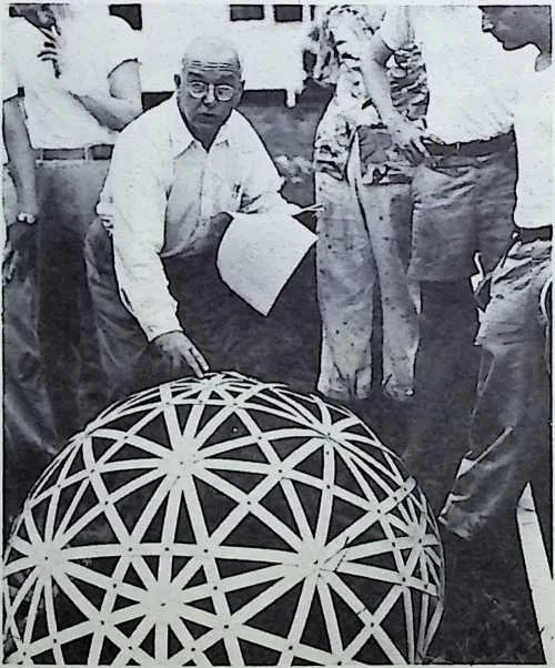
658 GEODESIC
659 INVENTION AND
660 DEVELOPMENT
661308 Unit of wire shown at left joins with identical components to form a triangulated finite convexity.
662309-310 Fuller taught Chicago Institute of Design students, 1948, to make 31-great-circle structures of prefabricated triangles, pentagons and hexagons, using struts, hubs, and cables for pan, separate skin and strut components.
663311 In July, 1948, Fuller, with Black Mountain College students, assembled a 48-foot-diameter hemispheric dome, of 31 great circles, the model of which is shown here. Fuller constructed the dome from 2-inch wide Venetian blind ribbon. He intentionally designed this structure so that its delicate system gently collapsed as it neared completion. He then fortified the individual chords of the triangular system with prismatically arranged additions of two more Venetian blind strips. Gradually the structure reassumed its domical configuration. The purpose of the demonstration was to show students—and through them the public—that so-called ”failure” of structures is not necessarily hazardous. The conventional strategy is to overbuild structures to make them safe, using materials so heavy that failures would bring fatalities; consequently the critical limit capabilities of complex structures are never known. Instead, Fuller here arranged to bring structure up to critical capability by the gradual addition of discrete increments. The result was that the safe structure of the 48-foot dome was accomplished with one-hundredth of the weight of material customarily employed.
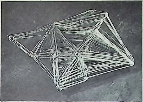
665312–316 Thirty-one-great-circle necklace structure of tubular beads and continuous internal cable net, folds up in tight package and unfolds to be tightened finally at its equator into hemispheric dome. The latter is shown in Pentagon Garden, Washington, D.C., February, 1949.
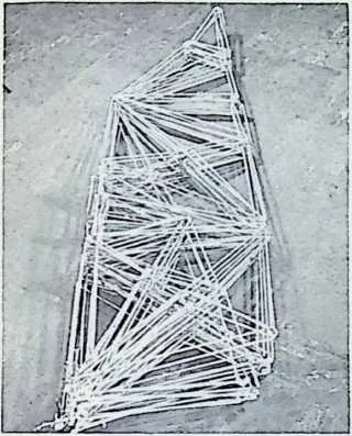
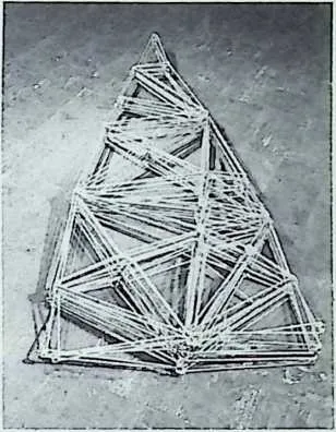
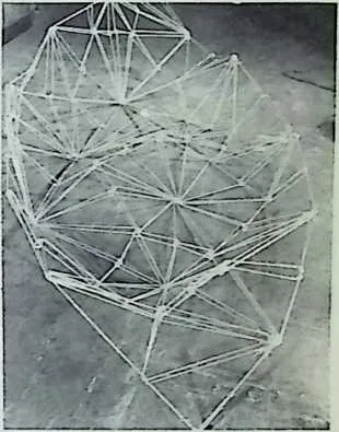
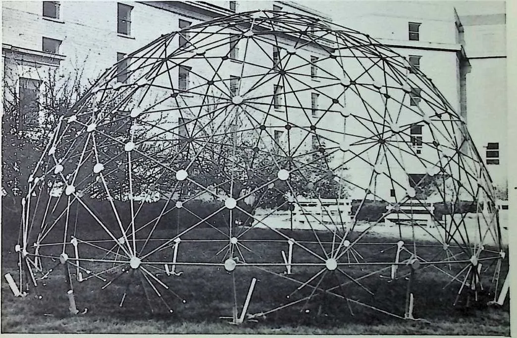
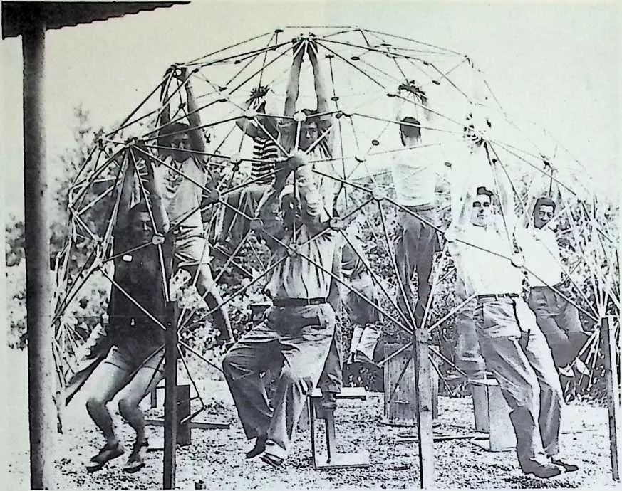
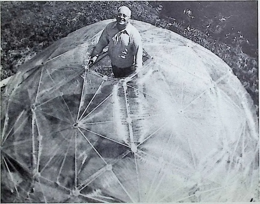
669317–318 Same necklace structure erected at Black Mountain College, North Carolina, 1949, demonstrated great strength. When covered with double heat-sealed, pneumatic, transparent skin, the structure maintained, in the sun, an interior temperature 10% below that of the outside air.
670 319–325 Fuller’s basic
671 Geodesic dome patent.
672 i®4 Kabuli** wa
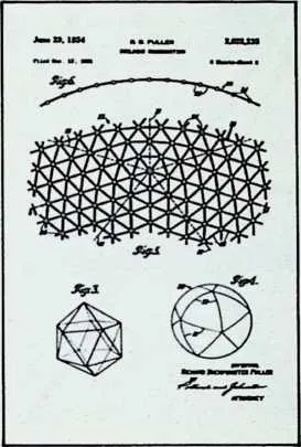
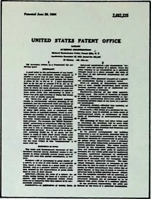
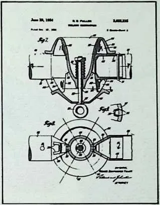

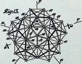
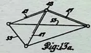
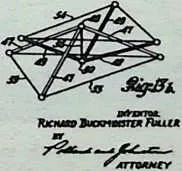
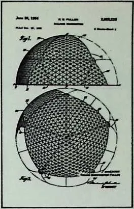
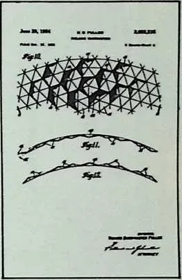

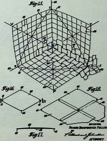
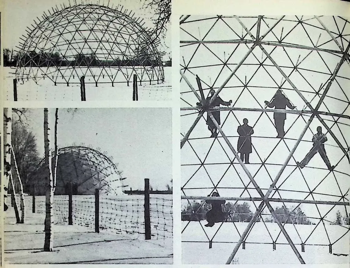
675 326-328 First large-size (50 feet in diameter) tube and skin structure, erected by the Fuller Research Foundation, Canadian Division, directed and calculated by Fuller’s former Institute of Design students, Jeffrey Lindsay and Don Richter, aided by Ted Pope, in Montreal, December, 1950.
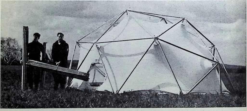
677 329 Two-frequency Geodesic for Arctic Institute, which went to Baffin’s Land in Labrador in 1951, shows hyperbolic parabola (positive-negative curvature) of outwardly tensed ‘‘Hypercat’’ skins which inhibit all flutter.
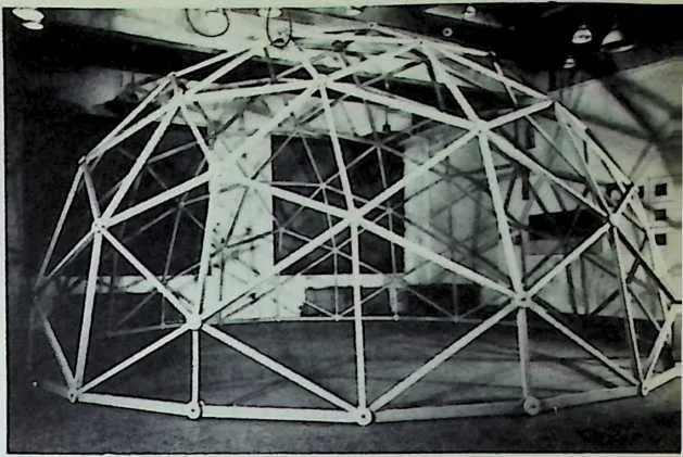
679330 Three-quarter-sphere, 16-frequency, welded steel wire Geodesic, 20 feet in diameter, by Fuller and Don Richter, Lawrence, Long Island, 1951.
680331 First wood strut Geodesic, by Zane Yost, Massachusetts Institute of Technology, 1951-
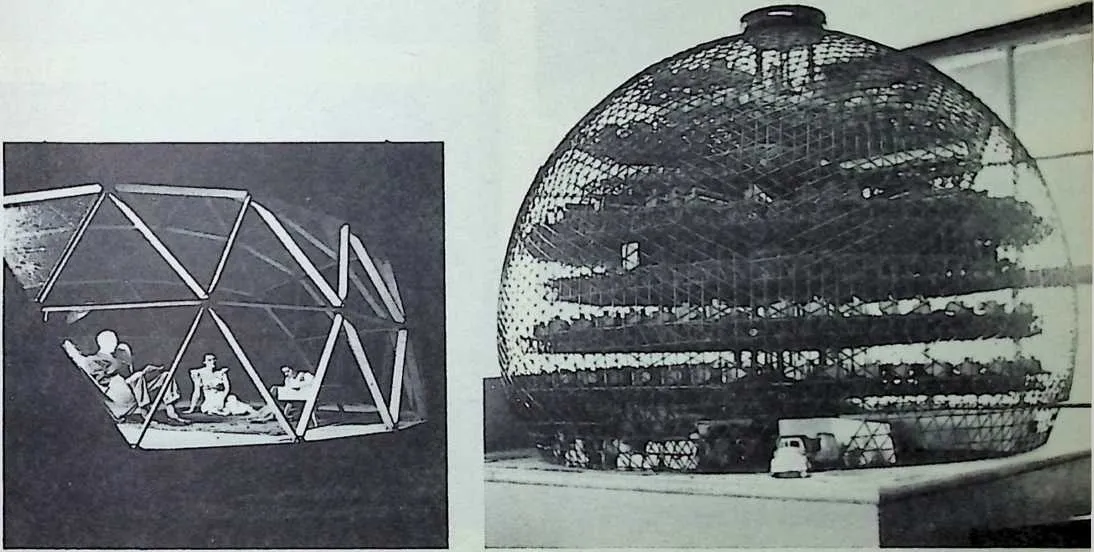
682 332 First wood and plastic Geodesic, by Jeffrey Lindsay, Montreal, 1951.
- 333.
- Model of Geodesic-covered, automated cotton mill with Octet Truss floors, by Fuller and students, North Carolina State College, 1951.
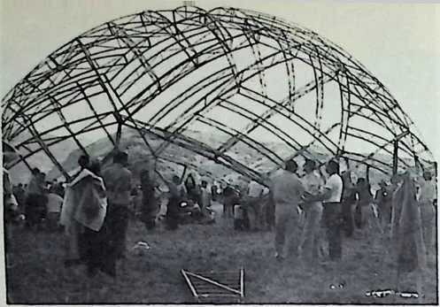
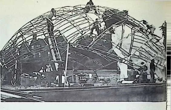
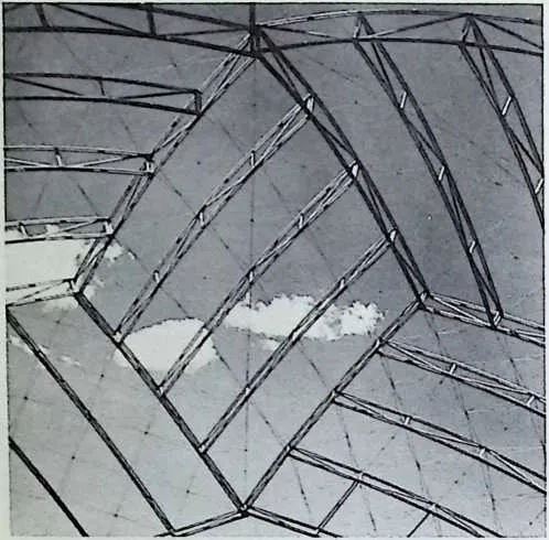
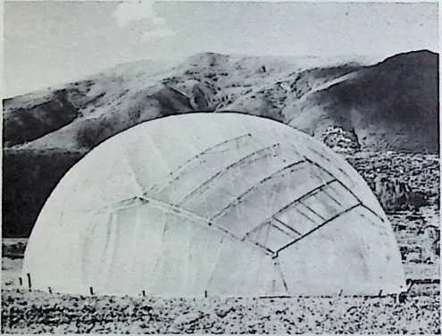
- 334.
- Fuller’s University of Minnesota students produced 36-foot Geodesic and assembled it in an hour and a half, at Aspen, Colorado, 1952.
- 335.
- Close-up of University of Minnesota dome, Aspen, Colorado.
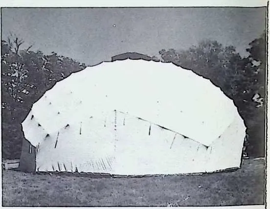
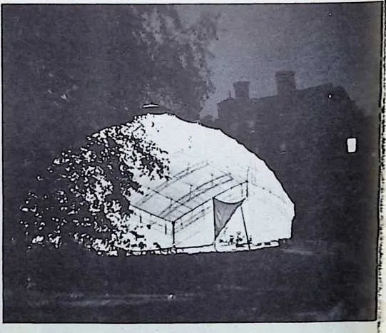
688689336 University of Minnesota Geodesic, covered with plastic skin, Aspen, Colorado, June, 1953-
690337–339 University of Minnesota Geodesic, trail-ered to Woods Hole, Massachusetts, and assembled, July, 1953-
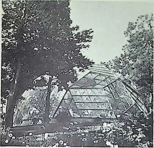
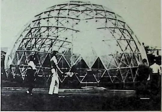
692340 Fifty-five-foot, wood and Mylar, hyperbolic parabola Geodesic restaurant owned by architect Gunnar Peterson, Woods Hole, Massachusetts, 1953-54. (This picture is also shown on facing page of chapter on Geodesic Structures.)
693341 Thirty-six-foot, wood and Mylar hemisphere, University of Oregon, March, 1953. It was fabricated by 40 students working three shifts for eight days. This was the first structure to be covered by Mylar.
694 342–343 Thirty-six-foot, transparent Geodesic ‘‘Growth House,’’ fabricated by North Carolina State architecture and agricultural science students, 1953. The double-skin dome slid upwardly from its foundation to increase base ventilation through screened accordion opening 18 inches in height.
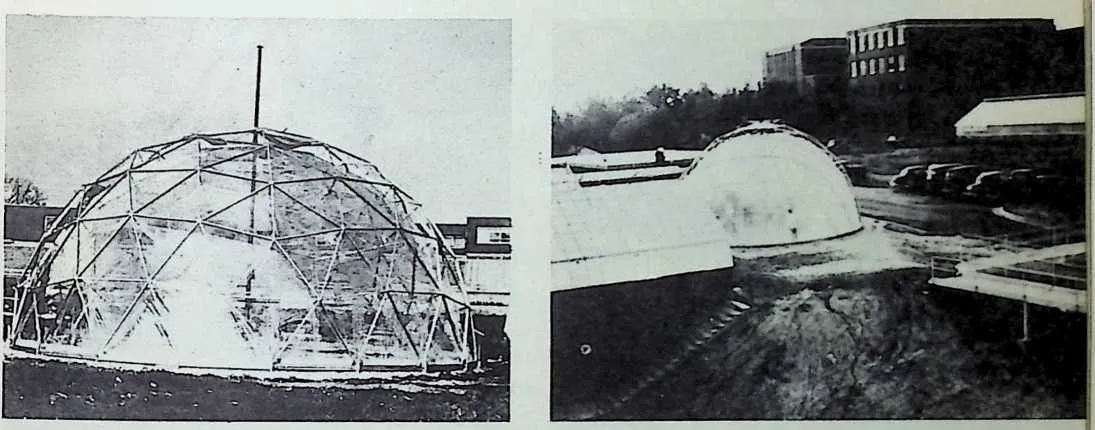
696 344 University of Michigan, Architectural Department Geodesic dome, 1954.
697 345 Washington University, St. Louis, Architectural Department Geodesic, 1954.
698346–347 ”Dynamic Dome,” designed in a 1954 University of Michigan research and development project, as a centrifuge umbrella to admit air while warding off rain.
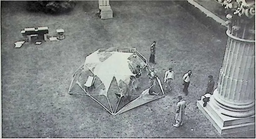
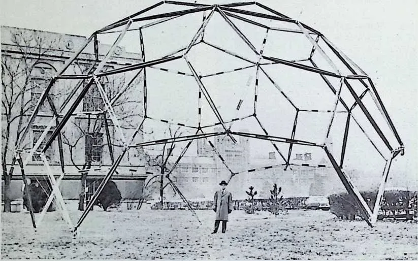
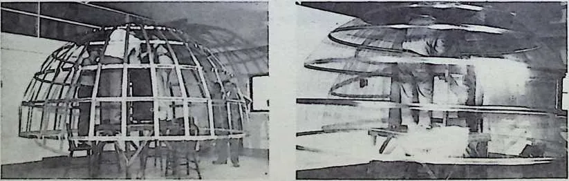
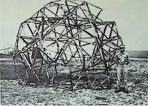
701702348 Virginia Polytechnic Institute, Architectural Department research project for U. S. Marine Corps, 1954-
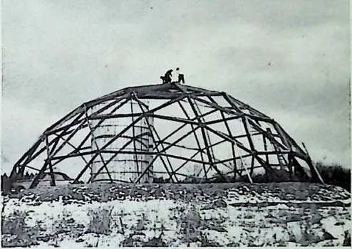
704705349 Laminated wood strut, polyester Fiberglass skin dome, 85 feet in diameter, built by Jeffrey Lindsay to be used as a barn, Montreal, 1954.
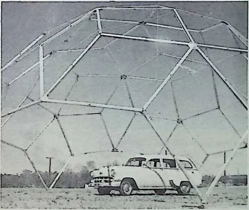
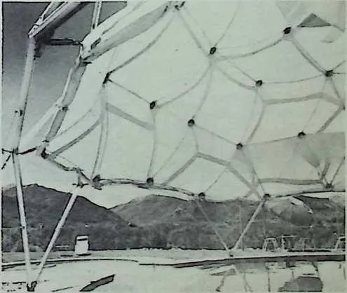
707350-351 Magnesium, five-eights-sphere Geodesic, 42 feet in diameter, erected to cover a naturally-heated swimming pool, Aspen, Colorado, 1954-
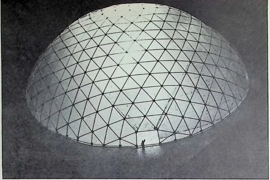
709710352 Model of 167-foot Geodesic for Southern Illinois University, 1955.
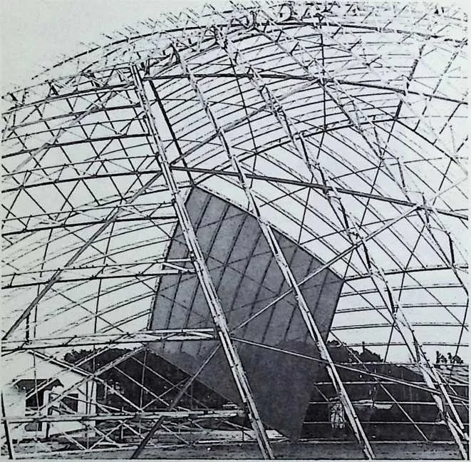
- 353.
- U. S. Air Force Academy’s acoustically-skinned, aluminum, planetarium dome, test-erected at Geodesic ‘‘dome farm,” Raleigh, North Carolina, before delivery to Academy’s Colorado Springs site, J957-This Spitz Planetarium Company’s dome and its Flint, Michigan, counterpart were prototypes for planetariums later produced by the Spitz Company. Specifications for the prototypes required l/32-inch tolerance between the horizontal and vertical radii dimensions when domes were assembled because of the delicate astronomical instrument functions to be served by these planetariums.
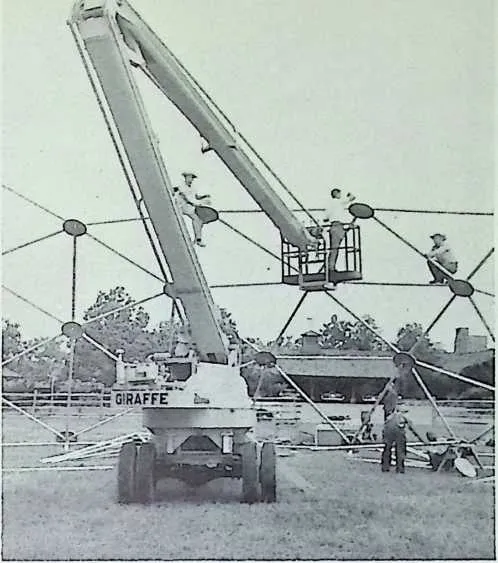
- 354.
- Giraffe crane speeded erection of 114-foot Geodesic pavilion at Winthrop Rockefeller’s Winrock estate, Hot Springs, Arkansas, 1956.
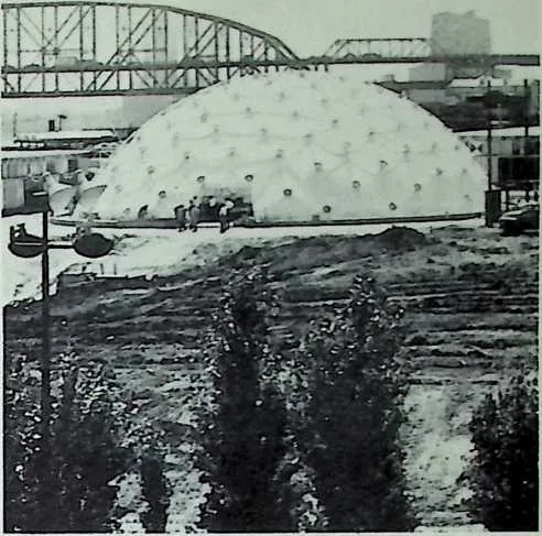
- 355.
- One-hundred-foot Geodesic pavilion was built for the mid-continent jubilee, St. Louis, Missouri, on the old fair grounds on the Mississippi River, 1956. This dome now covers the skating rink at Detroit’s Northland Shopping Center.
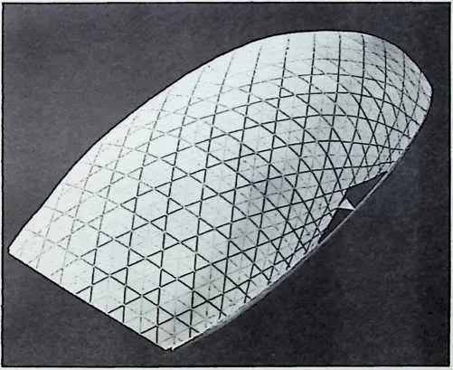
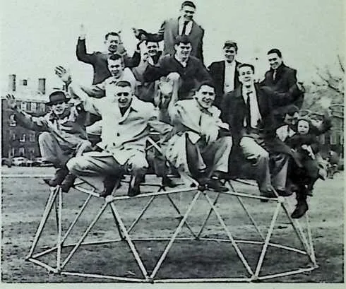
715 357 Geodesic ‘‘Playdome,’’ which went into mass production in 1957, supports group of Harvard students.
- 356.
- ModeV of ovaloid Geodesic hockey rink enclosure proposed for Andover Academy, Andover, Massachusetts, 1955.
716SKYBREAK DWELLINGS
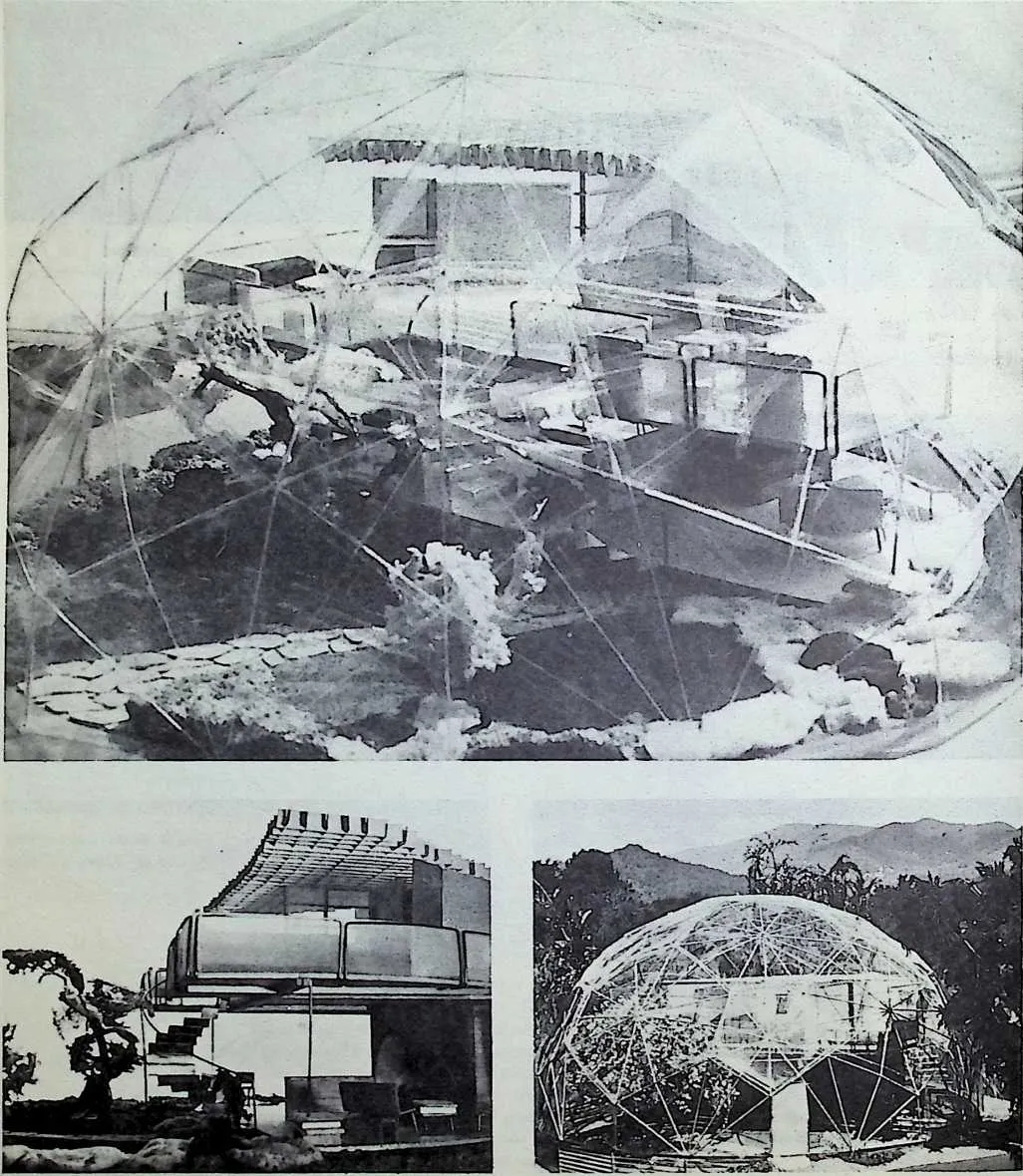
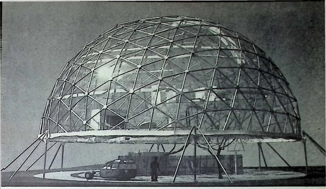
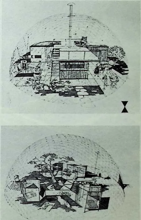
720358–363 Studies by Fuller and students of the ‘‘Skybreak Dwelling’’ potentials of Fuller’s domes. With complete grounds enclosed by a dome, eliminating rain, wind, snow and insects, houses themselves can be eliminated. Families can dwell in secondary pavilions within their gardens. The first picture shown here is an exterior view of a model developed for the U. S. Air Force in 1949. The second shows the interior of the same ‘‘dwelling.” The third is of a model constructed at Black Mountain College, North Carolina, in 1949. The fourth shows a model made by Fuller’s students at the Massachusetts Institute of Technology for the Museum of Modern Art where it was shown in 1952. The last two studies were developed by M.I.T. students in Fuller’s 1952 research project. The drawings are by John Rauma.
721 FORD DOME
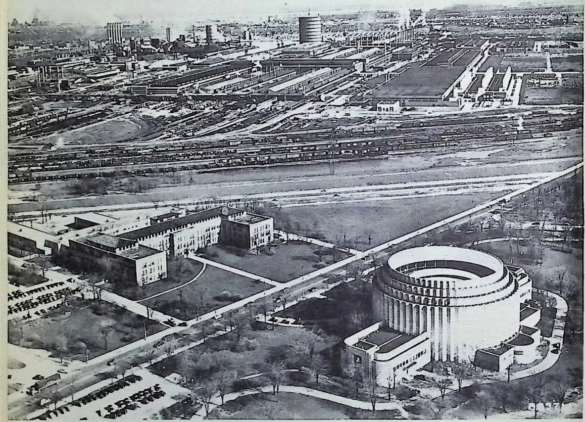
723724364 The famous Ford River Rouge plant. Shown at right foreground is the Rotunda building before the dome was constructed. In 1952, young Henry Ford wanted to dome over the Rotunda court—in respect for his grandfather’s wish—as a major feature of the company’s fiftieth anniversary in June, 1953. After he had been convinced by engineers that conventional domes were unobtainable within the limited time, and that such domes could not be supported by the lightly-built Rotunda building, Ford resorted to a Geodesic dome. Fuller designed, produced, tested, and installed the structure in four months using Ford Company facilities.
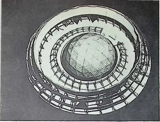
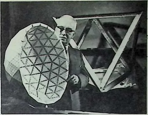
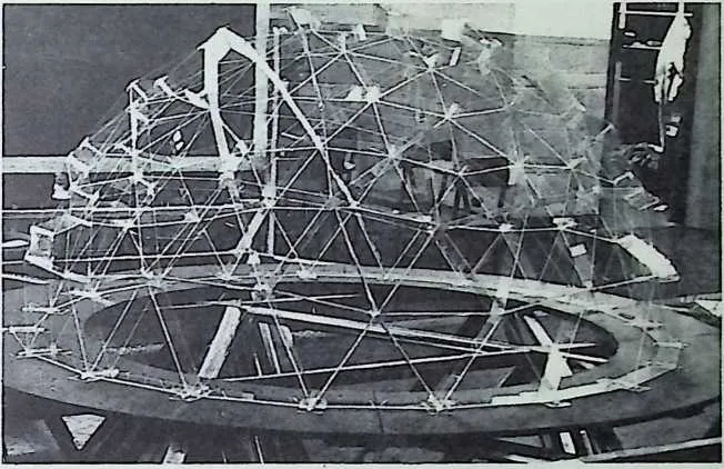
726 365 Model of assembly operation on Rotunda roof.
- 366.
- Fuller with model of the dome and its octahedral components.
- 367.
- Model of Ford Rotunda dome in polarized plastic, by University of Michigan students, disclosing the strain patterns of the structure.
- 368.
- Dome was assembled from the top down as a rotating, hydraulically-elevated umbrella. The workmen stood on a wide bridge installed above the Rotunda court.
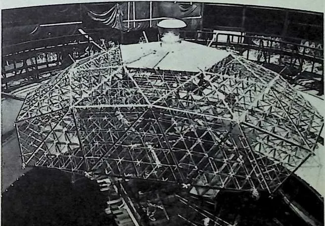
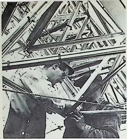
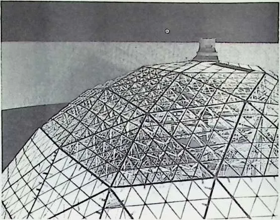
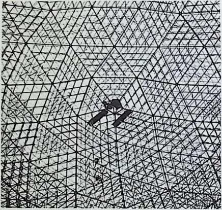
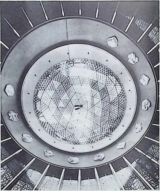
- 369.
- Workmen on the bridge, assembling components.
- 370.
- Ford Rotunda completed in April, 1953, two days before deadline.
- 371.
- View from beneath the completed dome, after installation of polyester Fiberglass. Two workmen can be seen climbing the structure. Note many concentric rings of the finite tension-inhibiting pattern, characteristic of the Octet Geodesic structure.
- 372.
- Life magazine’s 180-degree wide-angle lens looks upwardly at Ford Rotunda dome, under which the Ford Motor Company held its first and subsequent stockholder meetings. Ford Motor Company officials were as enthusiastic about the dome after its completion as they had been ‘‘gravely and most visibly skeptical before.’’ This first industrial use of Fuller’s on-the-shelf capabilities initiated the fast growing acceptance of Geodesic domes by government and industry. By 1959, approximately 1,000 domes had been built.
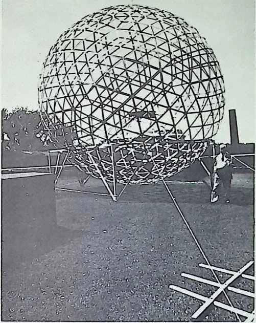
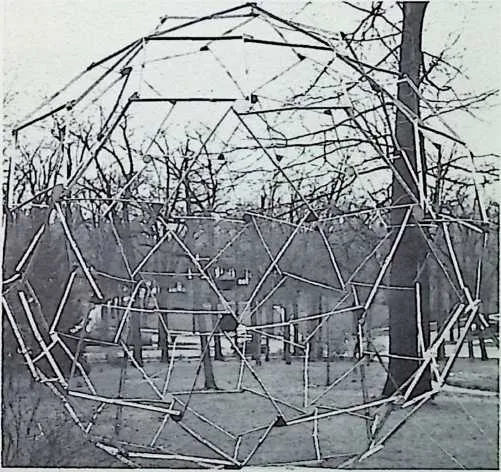
SEEDPOD FOLDABLE GEODESICS
- 373.
- Foldable components of Cornell 2o-foot Geodesic sphere, 1952.
- 374.
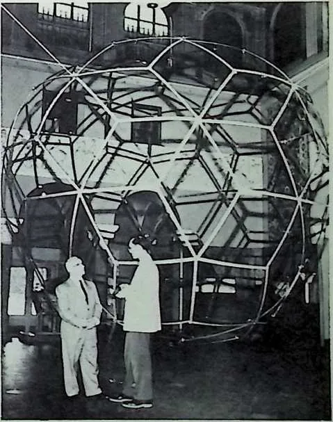 Foldable Geodesic, University of Michigan, Architectural Department,
1953.
731375 Foldable Geodesic, Oberlin College, 1953.
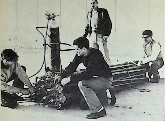
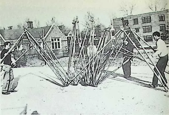
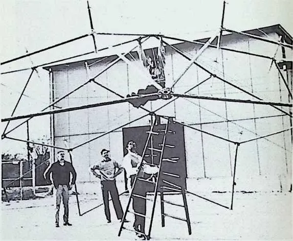
734376-379 Foldable Geodesic ”Flying Seedpod’’ project, Washington University, St. Louis, Missouri, 1954–55. Magnesium ball-jointed tripods, ball-jointed at their feet, were tensionally opened by piston-elevated masts, driven by 200-pound gas pressure in cylinders located at each vertex of the structure. As the wing-flyable bundle stood upright, a pulling lanyard permitted the 42-foot dome to open and erect itself in 45 seconds. This experiment initiated Fuller’s subsequent development of air-droppable and rocketable, remotely installable, controlled environments.
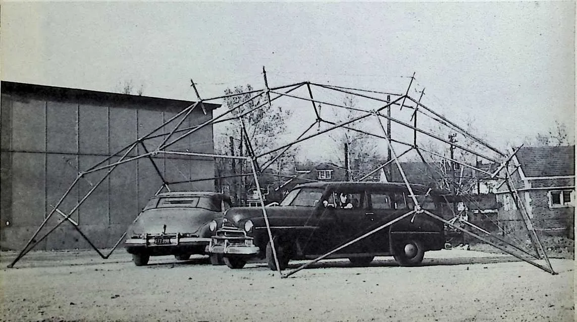
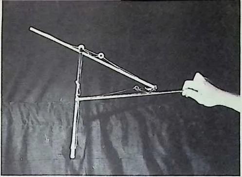
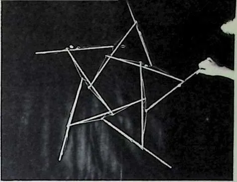
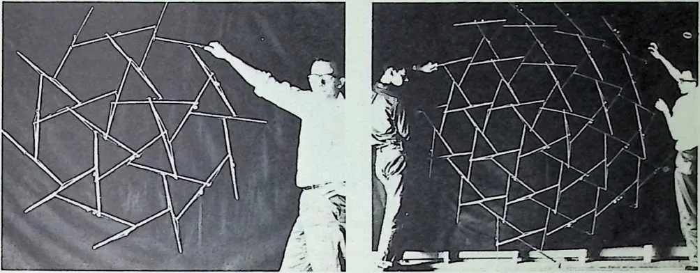
737380–383 Tensegrity marriage of tripod components eliminates the need for ball joints; permits parallel bundling of total components of large Geodesic structures suitable for moon installations.
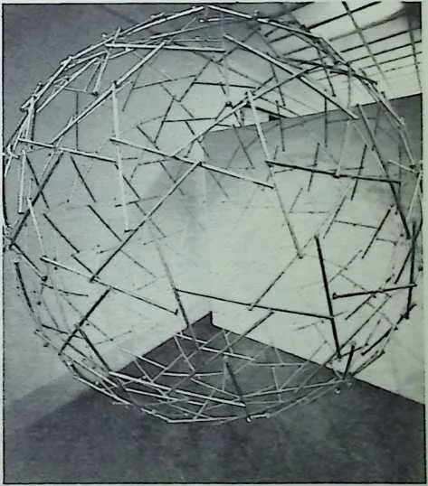
- 384.
- Parallel foldable Geodesic sphere, installed in the Metropolitan Museum of Art, New York,’summer of 1959.
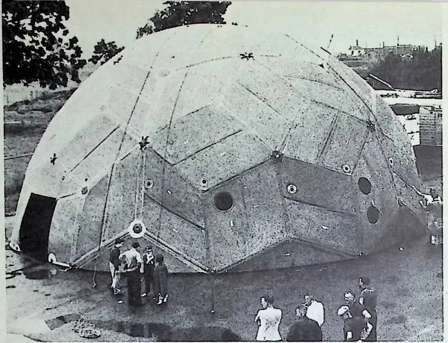
- 385.
- Fifty-five-foot, pneumatic, quilted double-skin Geodesic dome, developed and manufactured by Berger Brothers, New Haven, Connecticut, for the U. S. Air Force. A smaller unit by Berger Brothers floated on an ice island to the North Pole as a well insulated personnel shelter.
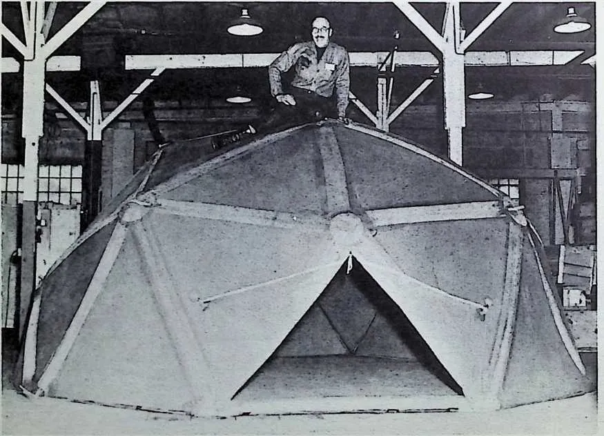
- 386.
- A man climbing on the pneumatically firm skin of the Air Force structure. The pressured air is held only within the skin structure, and not inside the dome which opens to the outside through regular doors and windows.
U.S. MARINE CORPS GEODESICS
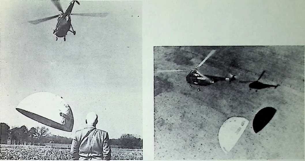
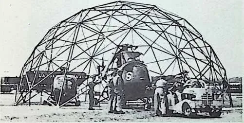
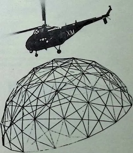
743744387–388 Fuller witnesses Marine Corps helilift of his 30-foot, wood and plastic Geodesic, at Orphan’s Hill, North Carolina, February 1, 1954. Marines flew dome at 50 knots without yaw, and returned to original spot without damage. This event inaugurated the Marine Corps’ rigorous investigation and eventual adoption of Geodesic structures.
745389–390 Three-helicopter magnesium hangar is being evacuated and lifted by its own helicopter.
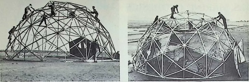
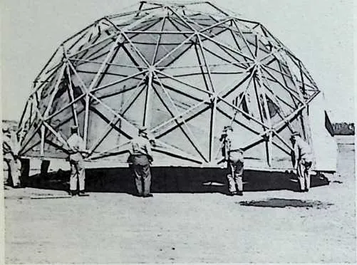
748391–393 A year of daily test assembly of Geodesic domes demonstrated that the structures could be assembled by green crews of Marines in an average of 135 minutes.
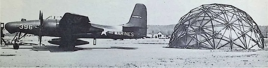
750751394 At the last assembly of the year, the dome is anchored firmly to the ground. Two 3,000 h.p. driven propellors of an anchored airplane provided day-long slam loads on the dome of 120 m.p.h. winds. The dome never fluttered.
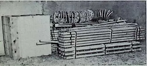
753395 Components for standard Marine Corps personnel and hangar structures, manufactured by Magnesium Products of Milwaukee.
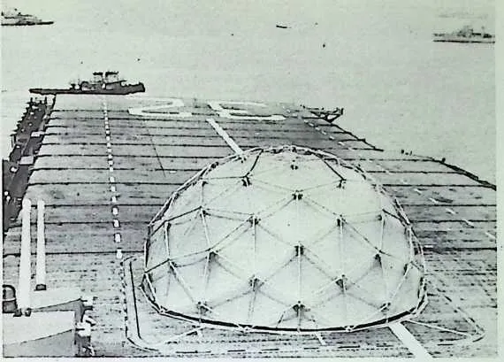
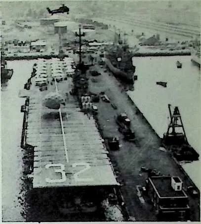

755396–400 Geodesic shown first on carrier’s flight deck, where helicopter lifts and flies it away at 60 knots to effect beachhead maintenance cover for aircraft.
757401-403 U. S. Marine Corps encampment, at National Air Show, Philadelphia, Labor Day, 1956, demonstrated mock beachhead landing under simulated atomic bombing conditions. Twin helilift brought Geodesics in ahead of Marines, who came by helicopter from aircraft earner Ticonderoga, moored in the Delaware River.
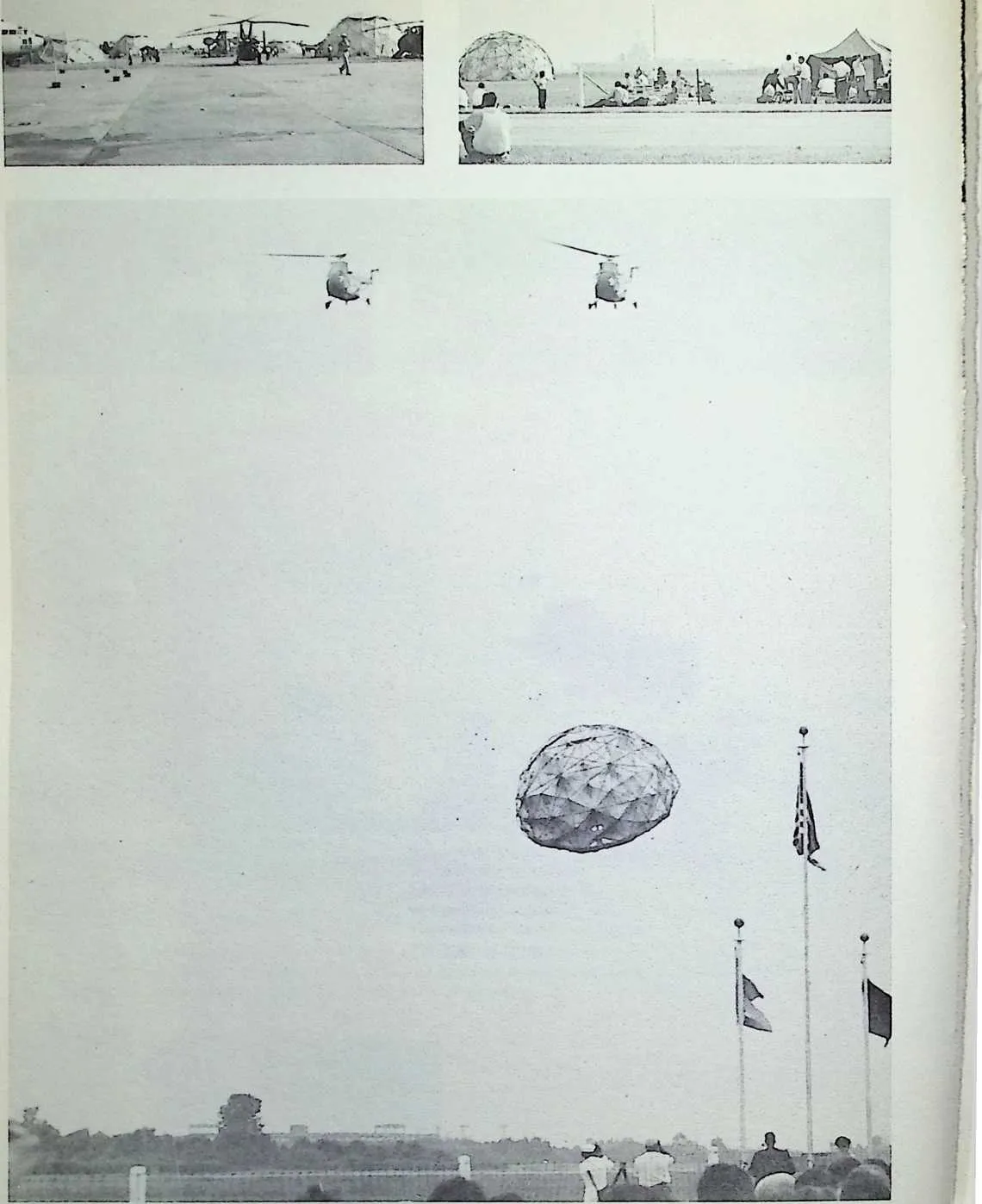
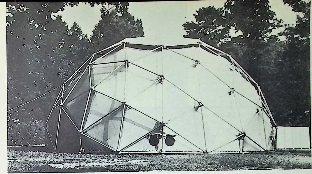
760761404 Clean-up model of Marine Corps Geodesic personnel shelter.
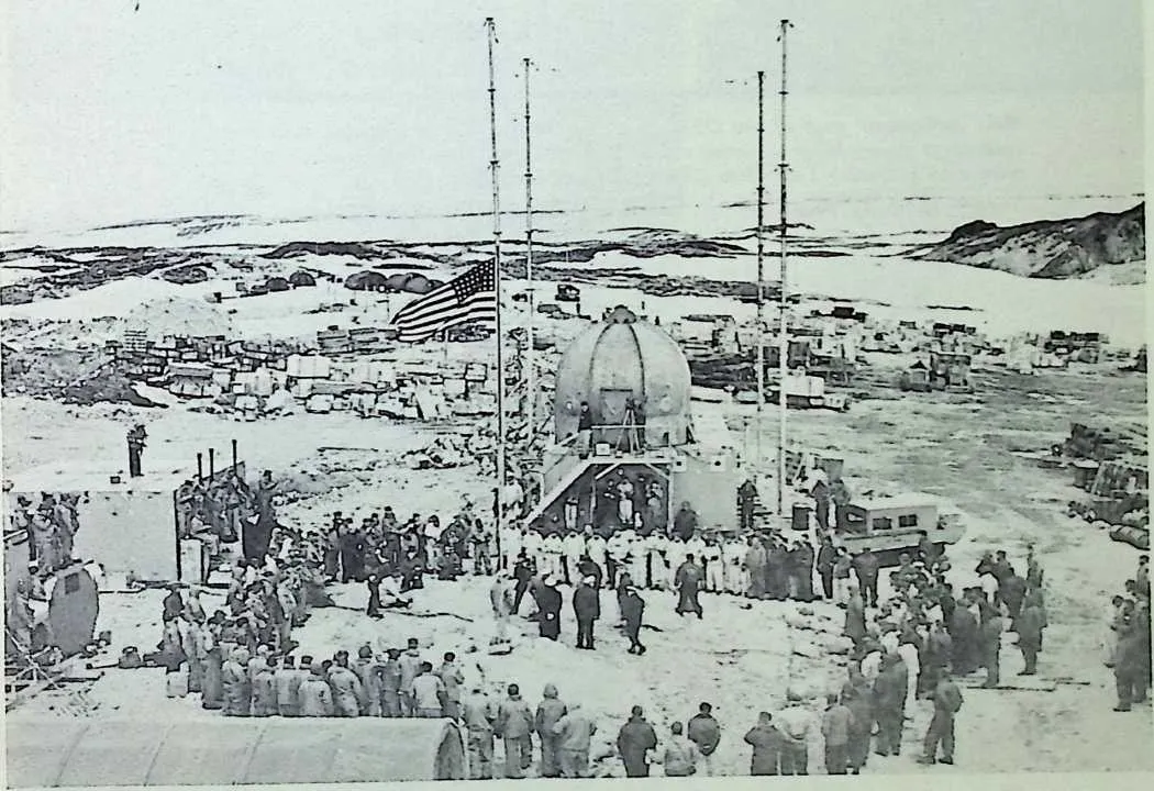
763764405 One of five Marine Corps Geodesic units, installed at Wilkes Land, Antarctica, in U. S. Geophysical Year base.
RADOMES
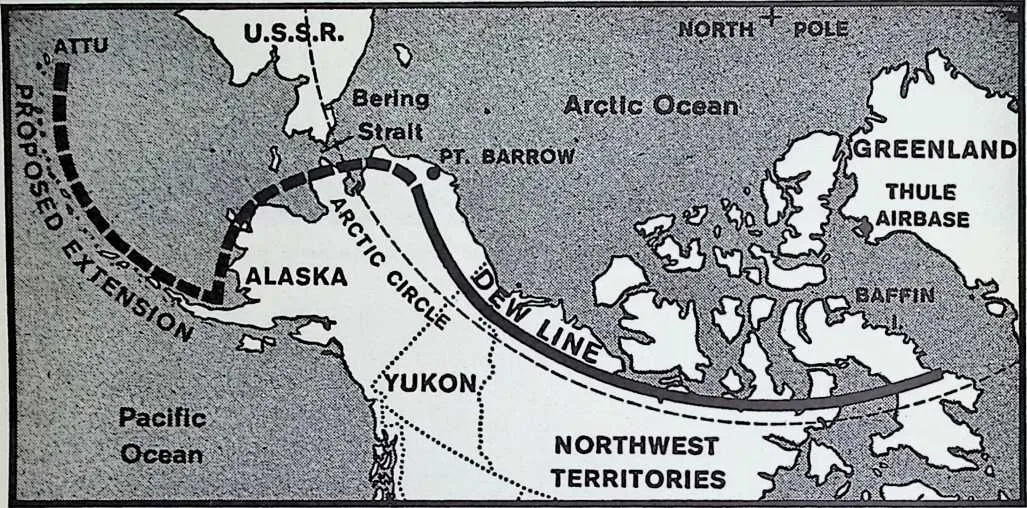
- 406.
- Schematic map of the DEW line, the Defense Early Warning system of radar installations comprising America’s first line of defense against surprise attack. Geodesic domes of polyester Fiberglass enclose the radar equipment of the entire system.
- 407.
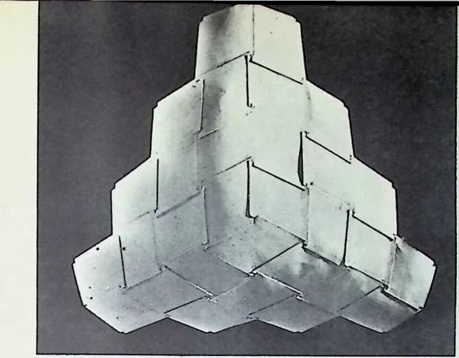
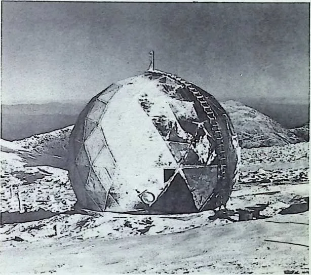 First test segment of polyester Fiberglass Geodesic, furnished
by Fuller on request of Lincoln Laboratory, U. S. Air Force DEW line
development organization. After two years’ testing, sample encouraged
physicists to believe Geodesics might successfully replace inadequately
performing pneumatic enclosures.
766 209
- 408.
- First Geodesic radome, 30 feet in diameter, furnished by Fuller’s Geodesic company, withstood 182 m.p.h. wind, and refused to ice up in 2-year top-of-Mt.-Washington test.
767 409 Intermediary phase of hex-pent, 31-foot Geodesic dome, is lifted to top of Lincoln Laboratories.
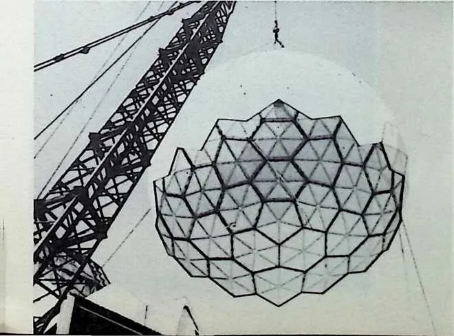
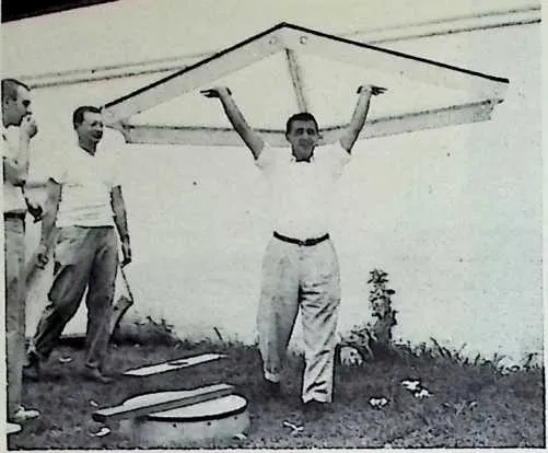
770410 Basic diamond component of Geodesic pantype polyester Fiberglass radome.
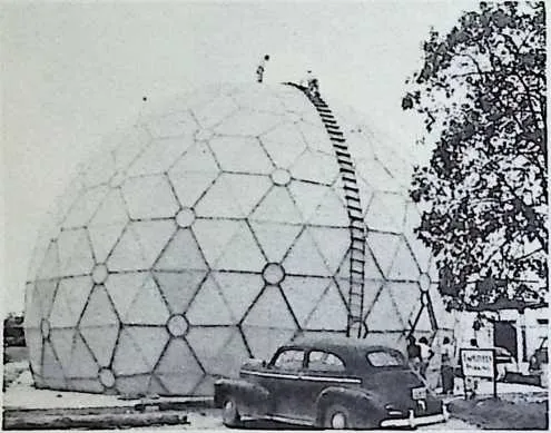
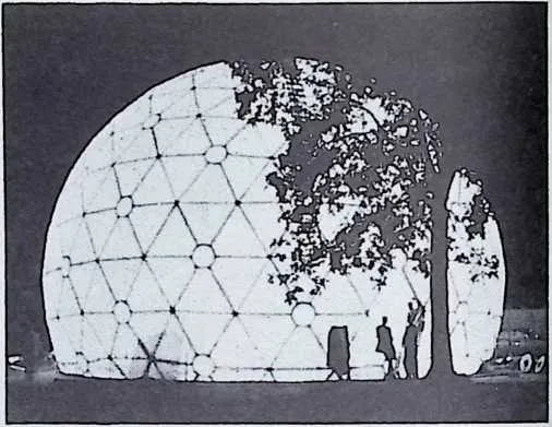
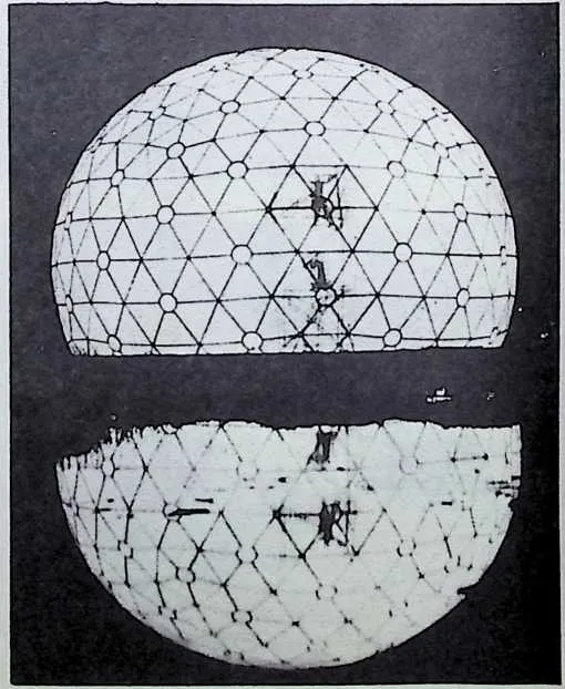
773411-413 Fully assembled 55-foot radome, ready for final testing which ended in its selection for the production unit.
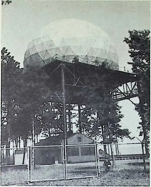
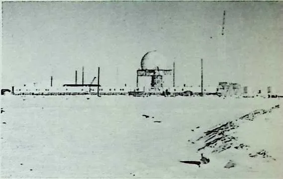
- 414.
- First production model radome to be delivered. It was installed at the Bell Laboratories, Whippany, New Jersey, 1956.
- 415.
- Geodesic radome installed at DEW line station by Western Electric, prime contractor for the DEW line.
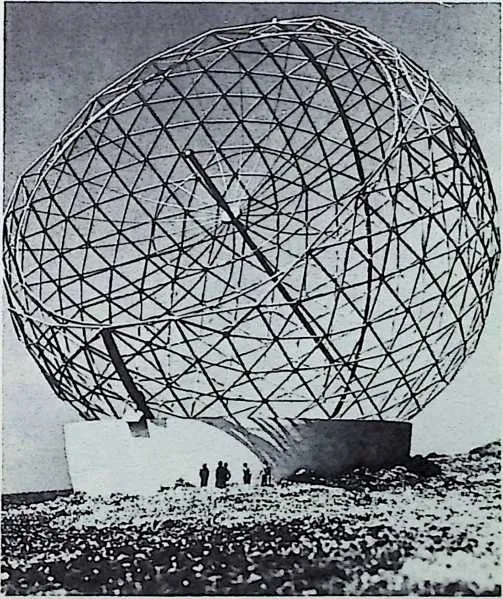
- 416.
- Model of parabolic mirrored Sky Eye Geodesic sphere produced in response to U. S. government inquiry preliminary to the development of a radio telescope, 600 feet in diameter.
776 PAPERBOARD DOMES
777 417-420 Fuller’s paperboard Geodesic dome patent.
778 421 Interior of first paperboard, 30-foot dome, installed by Fuller and students, Yale University Architectural School, 1951.

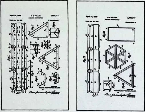
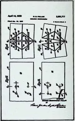
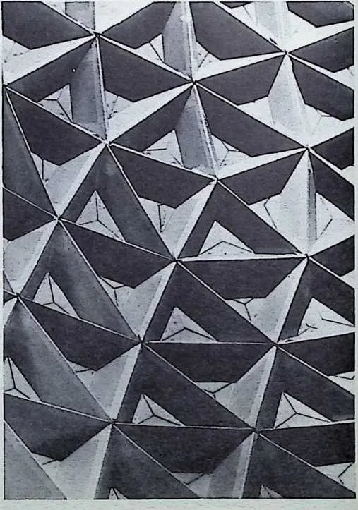
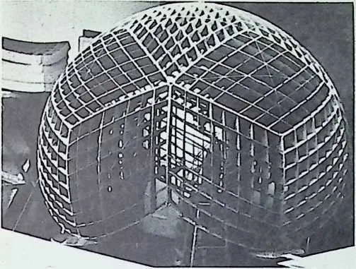
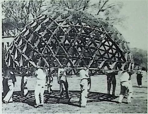
- 422.
- Paperboard, foldable, diamond honeycomb Geodesic dome, 1952.
- 423.
- Paperboard Geodesic dome, coated with polyester resin, Tulane University, 1954.
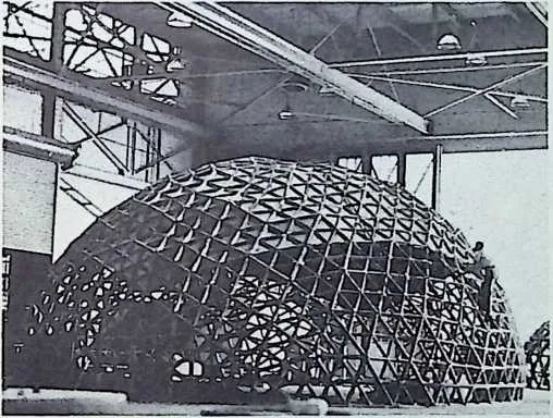
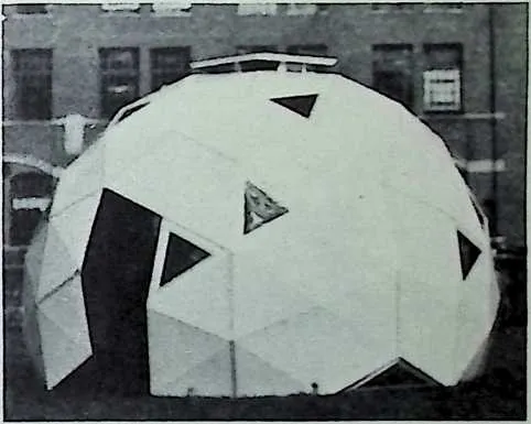
- 424.
- Polyester-resin paperboard Geodesic dome, North Carolina State College, 1954-
- 425.
- Three-quarter sphere, polyester-resin paperboard Geodesic dome, 14 feet in diameter, developed for U. S. Marine Corps, by University of Michigan students, 1954.
782426–430 Printed, scored, and cut blanks for 42-foot, double-skin, paperboard Geodesic dome for U. S. Marine Corps and Triennale of Milan, being assembled at Quantico, Virginia, Marine Corps Base, August, 1954-
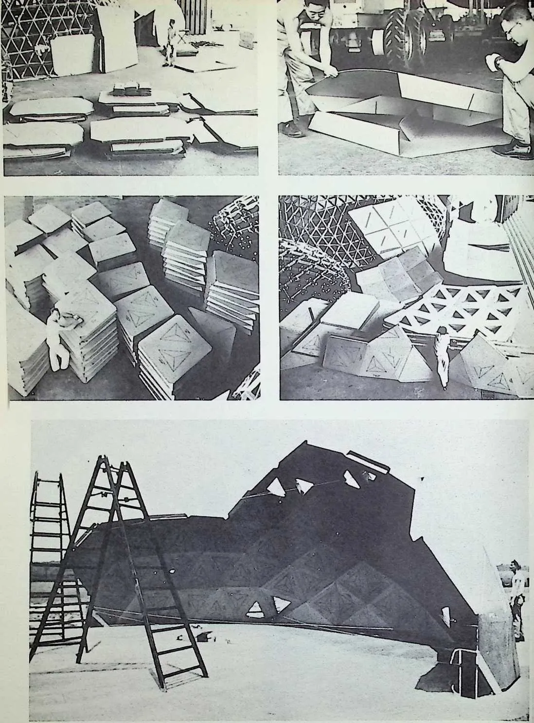
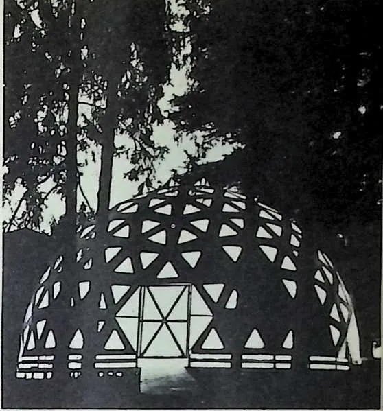
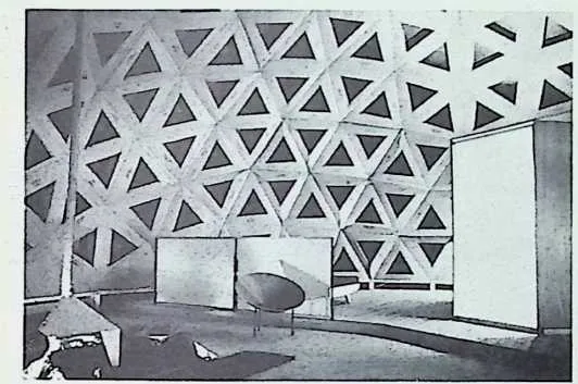
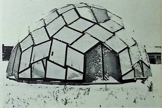
786431-433 Forty-two-foot, paperboard Geodesic installed in old Sforza garden, in Milan, where Leonardo da Vinci once worked. The two Geodesic paperboard domes of 1954 (one of which was furnished as a bachelor’s apartment) won the Gran Premio of the 1954 Triennale.
787434 Aluminum-clad paperboard dome erected by architectural students of McGill University with materials donated by Aluminium Company, Ltd., successfully endured Canadian winter, 1957.
788 PLYDOMES
789 435-436 Two-frequency
790 Geodesic plydomes, Des Moines, Iowa, 1957-
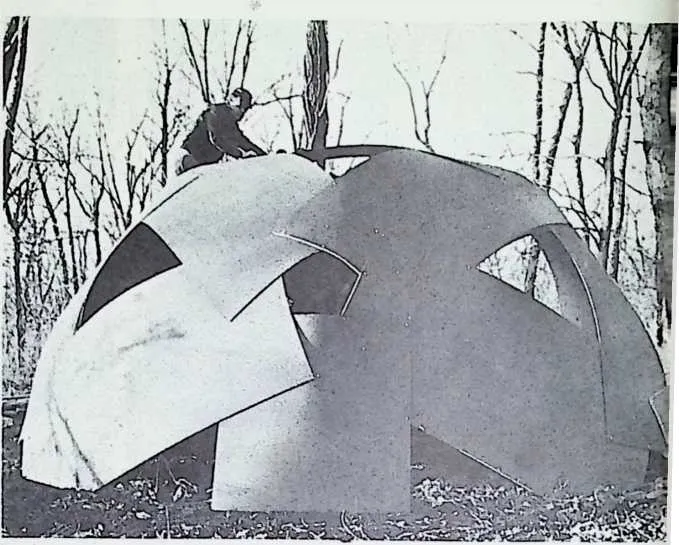
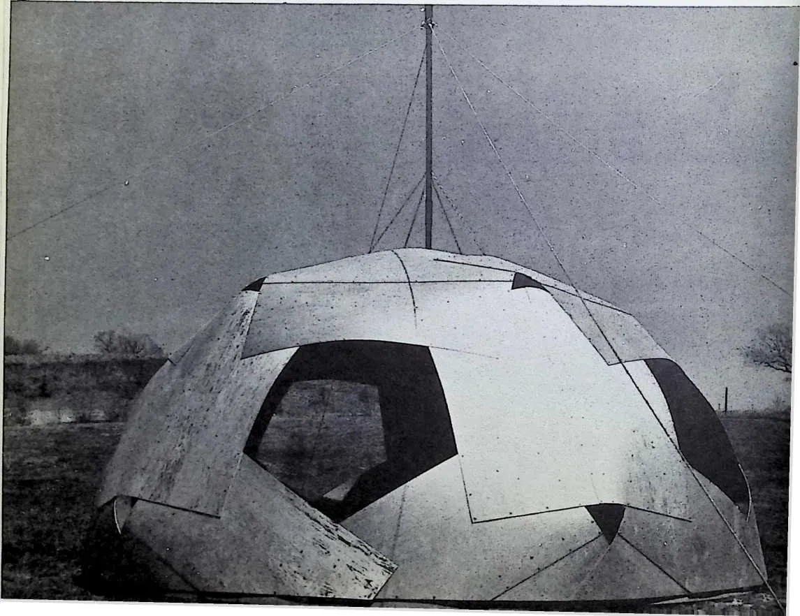
792 437 All the printed and punched ¥4 -inch Plywood components for a 42-foot dome arrive at site.
793 438-439 Forty-two-foot Plydome is erected.
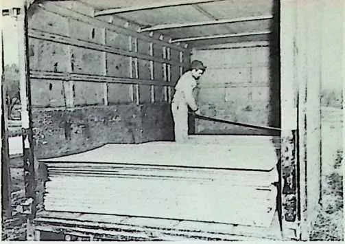
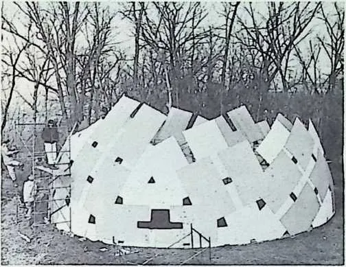
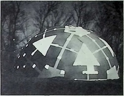
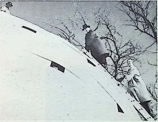
796440 Fuller and associates on top of ¥4-inch Plywood dome which has no internal frame. Flat sheets that permit five independent axes of bending, together constitute a spherical system when the necessary mathematics have been computed and the indicated join holes punched into boards.
797441–442 Geodesic farm shelter, Michigan State University, 1957. The second picture shows it housing a tractor.
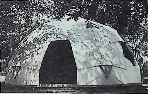
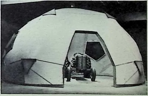
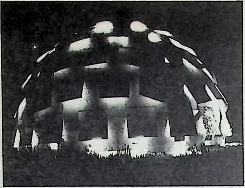
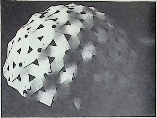
- 443.
- ‘‘Pine Cone’’ 42-foot Plydome Geodesic, installed by Fuller and Cornell University students, Ithaca, 1957.
- 444.
- Involute Plydome, by T. C. Howard, Synergetics, Inc., 1957.
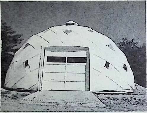
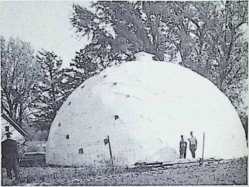
- 445.
- Shingled watershed Geodesic Plydome garage; Iowa, 1957.
- 446.
- Forty-two-foot shingled Geodesic Plydome barn on Iowa farm, 1957.
801 447 Geodesic Plydome chapel of Columbian Fathers adopted by them for leper colonies in the Philippines, Korea, and South Pacific Islands. The chapel has colored plastic windows.
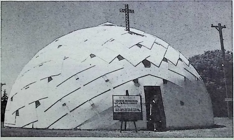
803 WWW
804448 449 Southern California children show enthusiasm for Plydome ”Playdomes’’
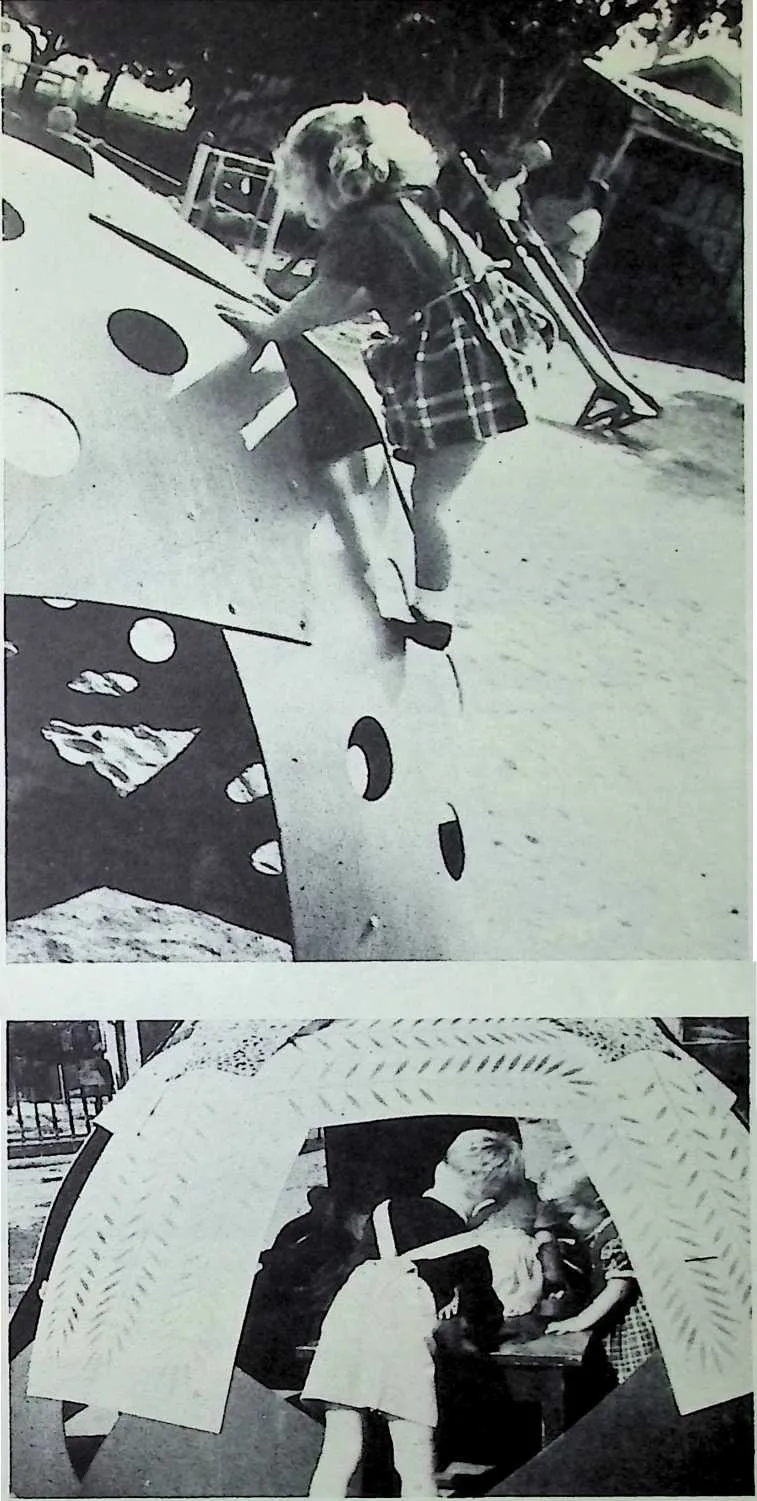
806 WORLD-AROUND STRUCTURES
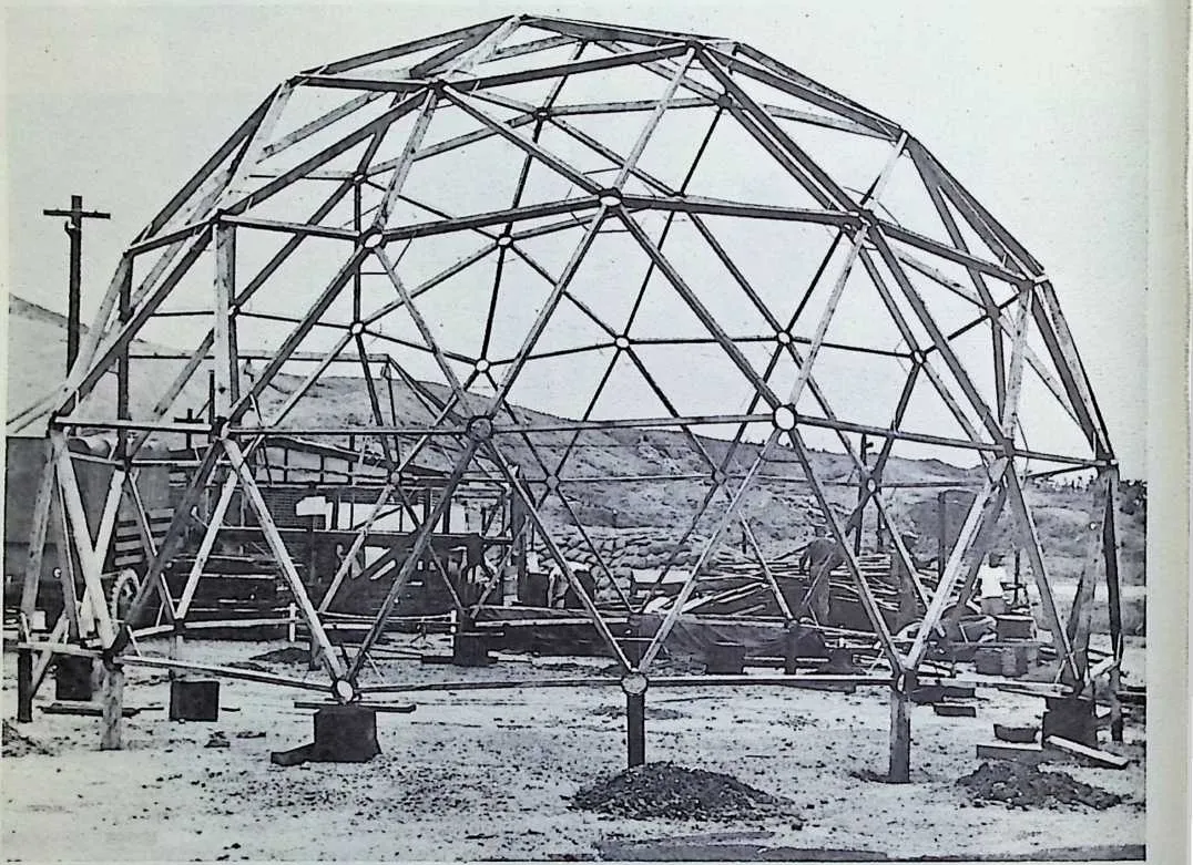
808809450 Geodesic dome to serve as bachelor officers’ quarters, U. S. Air Force, Korea, 1955-
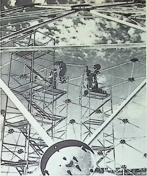
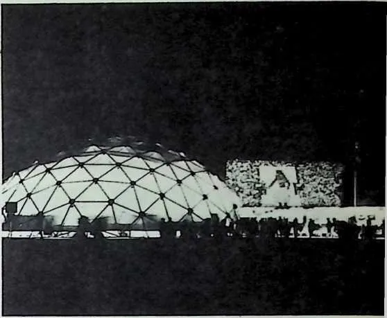
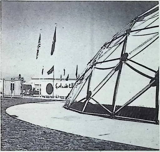
812451-454 U. S. loo-foot Geodesic pavilion assembled by Afghans, under direction of one American engineer in 48 hours for the Trade Fair at Kabul, Afghanistan, in August, 1956. The A fghans regarded Fuller’s Geodesic as a modern Mongolian yurt; consequently a native Afghan type of architecture.
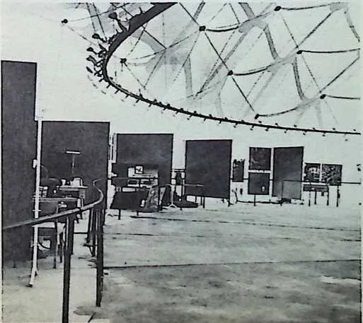
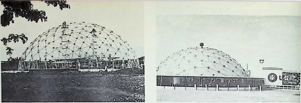
815816455–456 U. S. Geodesic pavilion, installed at Bangkok, Thailand, winter, 1956-1957.
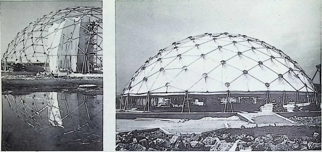
818457-458 U. S. Geodesic pavilion, first installed at Kabul, was airflown to successive sites; it is shown here at the World Trade Fair in Tokyo, 1957.
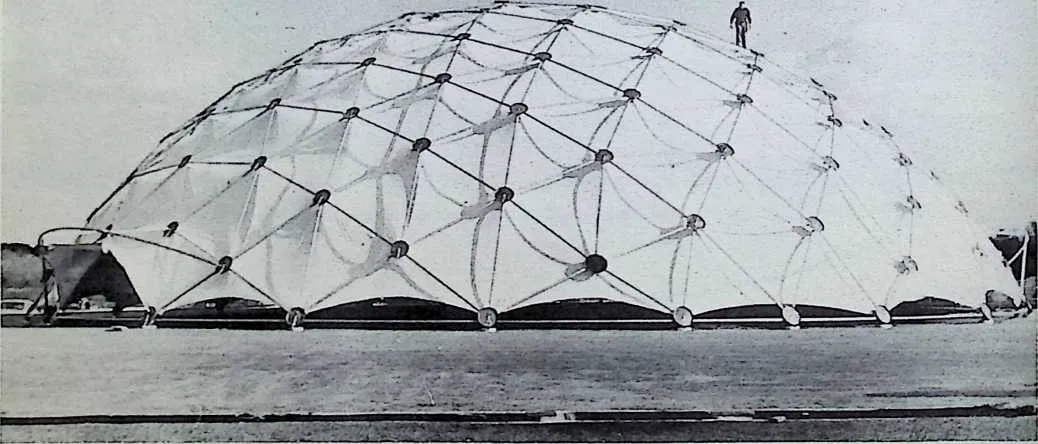
820459 U. S. 114-foot Geodesic pavilion at the 1958 Trade Fair in Poznan, Poland. This was the first trade fair behind the Iron Curtain.
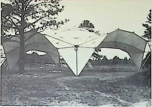
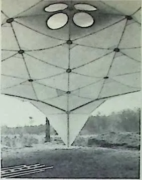
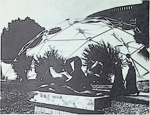
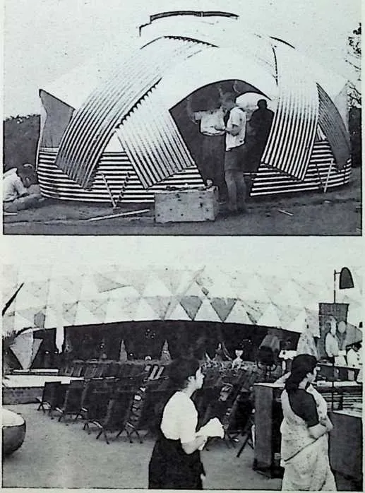
823460-461 Involute-evolute parabolic Geodesic, shown at Geodesic ‘‘Dome Farm,’’ Raleigh, North Carolina, prior to installation at Casablanca, Tunisia, and New Delhi.
- 462.
- Geodesic pavilion of the U. S. Department of Commerce won the Gran Premio at the Triennale in Milan. 1957.
- 463.
- Corrugated aluminum, 18-foot Geodesic dome, constructed by Fuller and students at University of Natal, at Durban, assisted by architectural students from the University of Capetown, South Africa, May, 1958. It was designed for the Zulus, whose cattle were eating them out of thatching grass required for their woven Indhlus. The corrugated aluminum ‘‘Indhlu’’ (as the dome is called by the Zulus), with plastic windows and Masonite polyethylene floor, complete with anchors, was produced at a materials cost of only $150.
- 464.
- Inside loo-foot Geodesic pavilion, manufactured and erected in Bombay, India, by the Calico Company, Indian licensees of Fuller, as a theatre for exhibiting textiles. The Calico Company has since erected a larger Geodesic display pavilion
824in New Delhi which is scheduled to be moved around the world.
KAISER GEODESICS
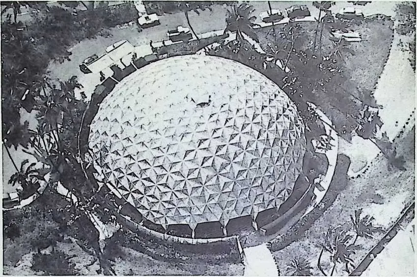
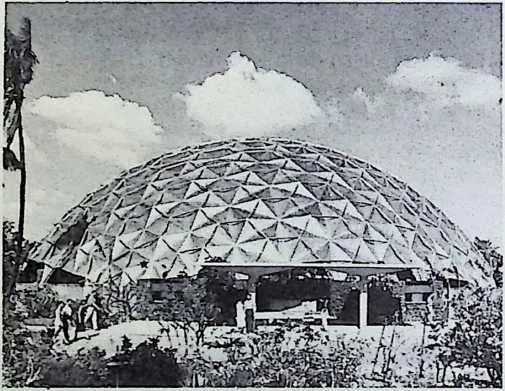
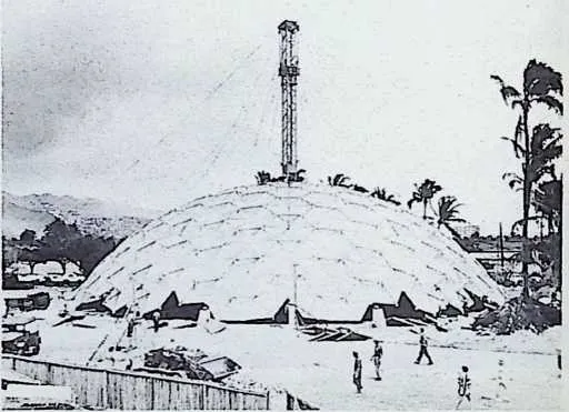
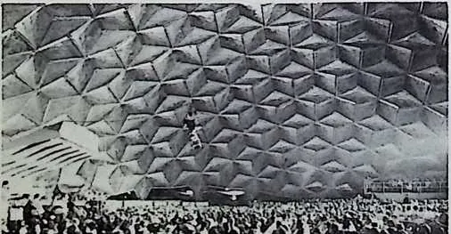
827465-468 Kaiser 145-foot Geodesic dome, manufactured in Oakland, California, and erected in 22 hours, in Honolulu, Hawaii, February, 1957. At the 22nd hour, the Hawaiian Symphony Orchestra and audience entered; the concert was completed within 24 hours of Honolulu landing of the dome’s components. The orchestra conductor pronounced the acoustics ”the best in his experience.”
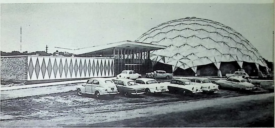
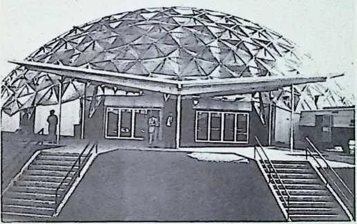
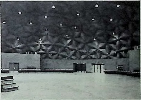
829469–470 Kaiser 145-foot Geodesic municipal auditorium, Virginia Beach, Virginia, 1957.
830471 Kaiser 145-foot Geodesic municipal auditorium, Borger, Texas, 1957.
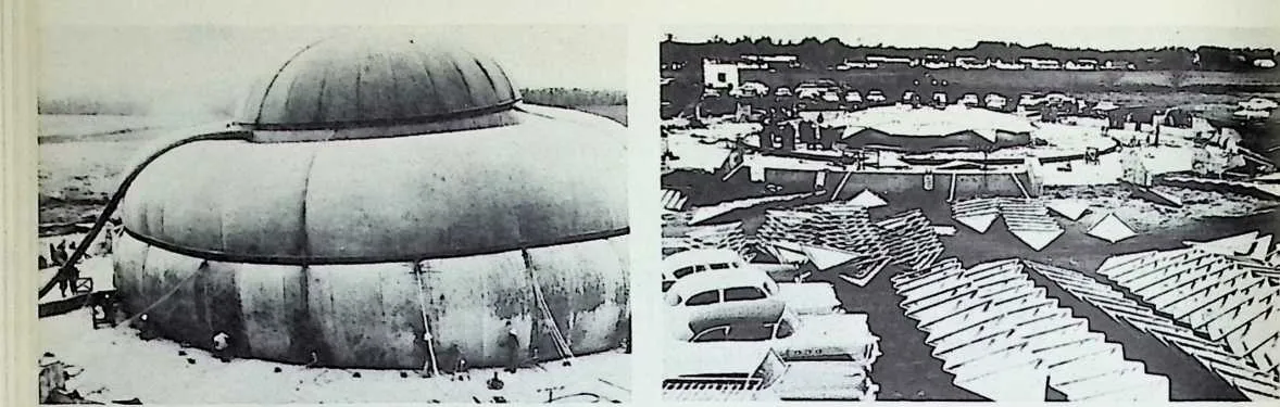
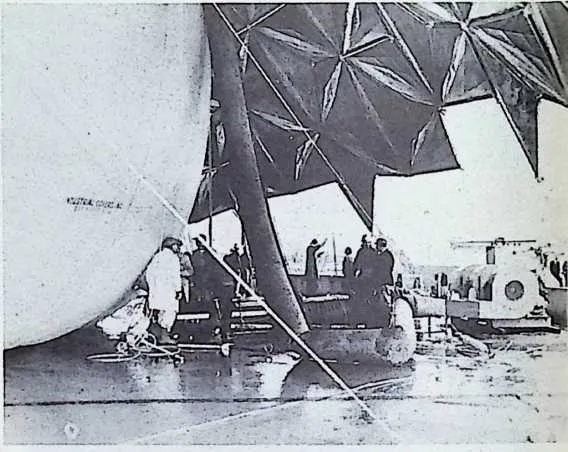
833472–475 Kaiser 145-foot Geodesic erected over a progressively inflated doughnut balloon, 1958.
834This structure is used as a grainery-filling equipment-manufacturing plant in Abilene, Kansas.
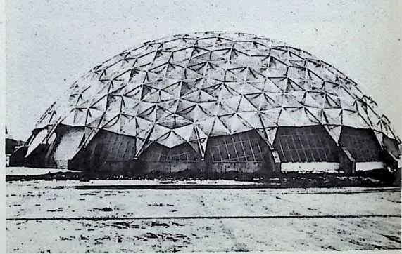
836 476–477
837 theatre-in-the-round, Fort Worth,
838Casa Manana Kaiser 145-foot Geodesic
839 Texas, 1958.
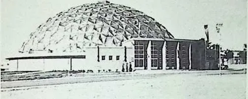

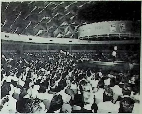
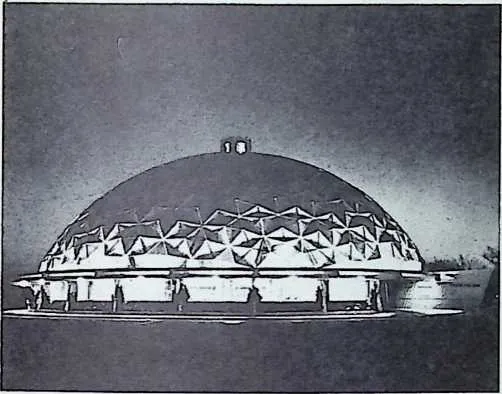
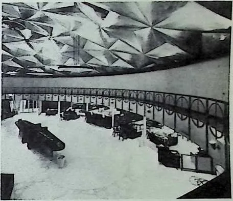
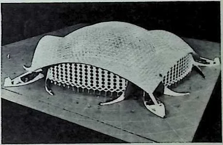
842478–479 Kaiser 145-foot Geodesic serves as Citizens State Bank, Oklahoma City, Oklahoma, 1958. Architects: Bailey, Bozalis, Dickenson, and Roloff.
843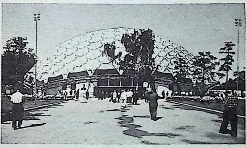 481 Kaiser 407-foot Geodesic sports palace planned for erection in
Oklahoma.
844 480 Kaiser 200-foot Geodesic, erected as the U. S. main pavilion at the American exchange exhibit in Moscow, 1959.
UNION TANK CAR COMPANY GEODESICS
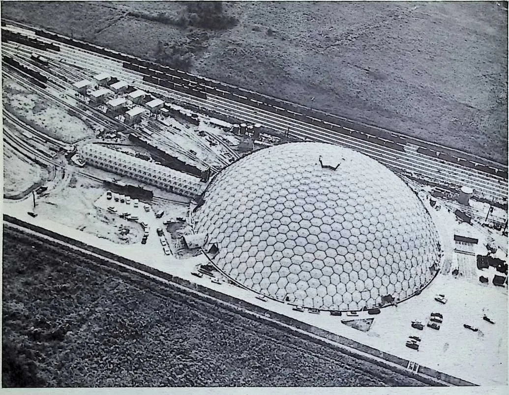
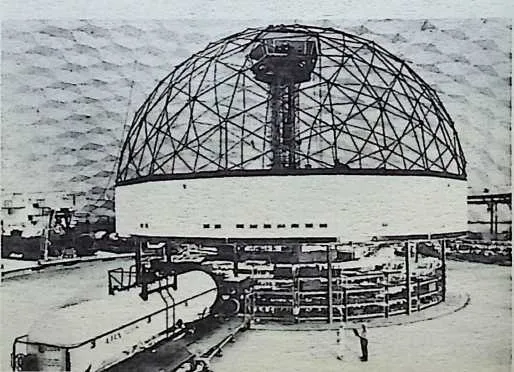
847482-483 Exterior and interior of all-steel Union Tank Car Company’s Geodesic dome, 384 feet in diameter and 116 feet high. It was opened in Baton Rouge, Louisiana, October, 1958, as car rebuilding plant. At that time it was the largest clear-span enclosure ever built anywhere.
8488497
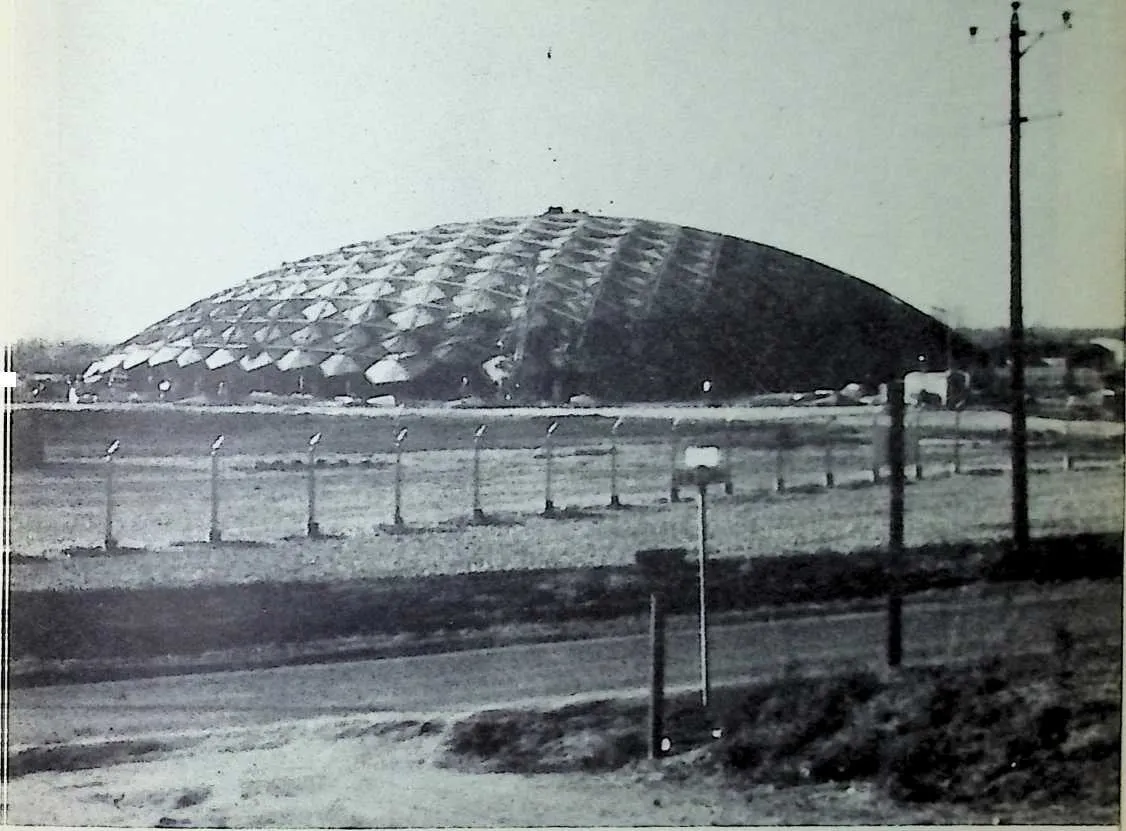
- 484.
- Union Tank Car Company’s second Geodesic, 354 feet in diameter, marketed by their Graver Tank Division, as the ”Union Dome,” under erection by pneumatic cushion lift, at Wood River, Illinois, winter, 1958--39.
AMERICAN SOCIETY FOR METALS STRUCTURE
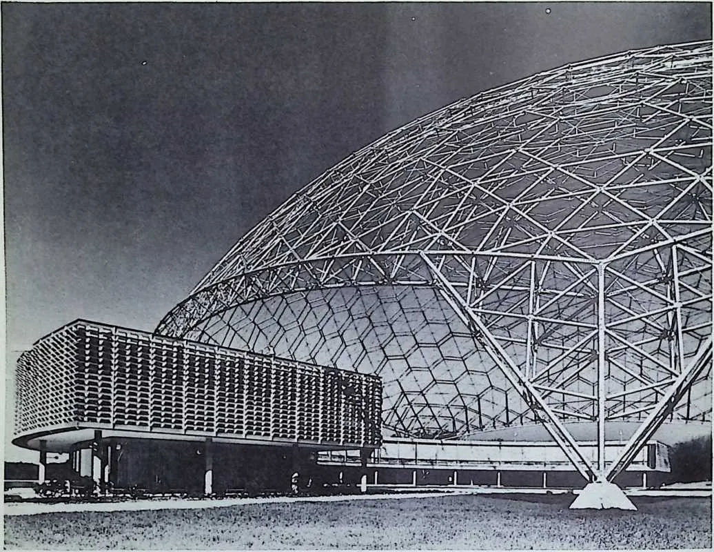
- 485.
- Hex-pent, -wire-wheel truss, double dome, 250 feet in diameter, erected by the North American Aviation Company over the building and grounds of the new national headquarters of the American Society for Metals, Cleveland, Ohio, spring, 1959-John Kelly: architect. Engineering design: Fuller’s Synergetics, Inc.
LARGE-SCALE PLANS
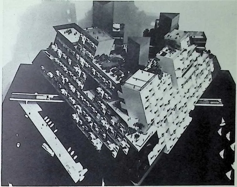
- 486.
- Over 80% of metropolitan areas with a population of one million or more are situated near bodies of water which are sufficient to accommodate floating cities. Most have a depth of water adequate for shipping (25-30 feet) and relatively sheltered harbors. At these depths a maximum average height of twenty stories can be floated.
853854With the sea as a highway an entire unit can be built in another location, such as a shipyard or drydock, and then towed to its site in one piece. Thus the economies of shop fabrication can be brought to bear on construction problems which are traditionally soluble only at the final site location.
855Triton City provides discrete neighborhood platforms up to four acres in area to house as many as 5,000 people. Its framework superstructure makes possible the flexible distribution of infilling components, such as apartments, classrooms, stores, and offices, with the prefabrication of elements providing assembly-line economies. Additionally, it will be possible to replace outmoded units or rearrange them without disturbing the overall disposition of the city. A whole neighborhood can be treated functionally as a single building with all utilities centrally provided.
856Because the megastructure constitutes a neighborhood entity, some new departures in aesthetics and safety can be realized. All parking is within the flotation, so that one major contemporary eyesore, the parking lot, is removed from view. Since wheeled vehicles are not permitted above the entrance level, the streets would be safe for pedestrians. Elevators and stairs in vertical towers, would have glazed sides, so that everyone inside is visible at all times.
857Triton City is designed to offer the best of two worlds: the dynamic quality of life in a milieu of urban high density and the view of immediately adjacent open space which is traditionally the province of suburban and rural areas. Since the community is intended as a city complement, it would have all the existing urban amenities, including entertainment, educational, and cultural activities to draw upon as well.
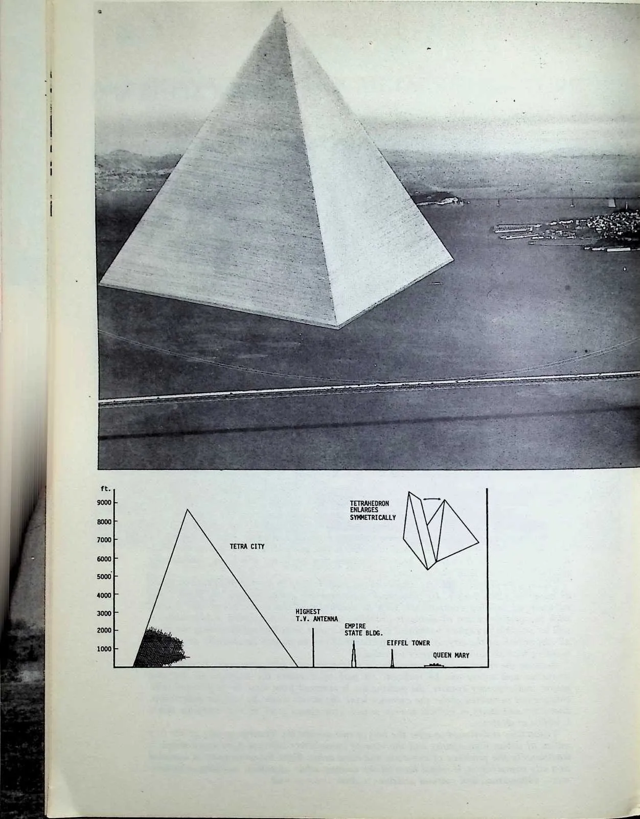
- 487.
- We find that a tetrahedronal city, to house a million people, is both technologically and economically feasible. Such a verti-cal-tetrahedronal-city can be constructed with all of its three hundred thousand families each having balconied ‘‘outside’’ apartments of two thousand square feet floor space. All of the machinery necessary to its operation will be housed inside the tetrahedron. It is found that such a one million passenger tetrahedronal city is so structurally efficient, and therefore so relatively light, that together with its hollow box sectioned reinforced concrete foundations it can float. Such tetrahedronal floating cities would measure two miles to an edge, and can be floated in a triangularly patterned canal. This will make the whole structure earthquake-proof. The whole city can be floated out into the ocean to any point and anchored. The depth of its foundations will go below the turbulence level of the seas so that the floating tetrahedronal island will be, in effect, a floating triangular atoll. Its two mile long ‘‘boat’’ foundations will constitute landing strips for jet airplanes. Its interior two mile harbor will provide refuge for the largest and smallest ocean vessels. The total stuctural and mechanical materials involved in production of a number of such cities are within feasibility magnitude of the already operating metals manufacturing capabilities of any one company of the several major industrial nations around the earth. The tetrahedron city may start with a thousand occupants and grow symmetrically to hold millions without changing overall shape though always providing each family with 200 sq. ft. of floor space. Withdrawal of materials from obsolete buildings on the land will permit the production of enough of these floating cities to support frequently spaced floating cities of various sizes around the oceans of the earth. This will permit mid-ocean cargo transferring and therewith an extraordinary increase of efficiency of the inter-distribution of the world’s raw and finished products as well as of the passenger traffic. Three quarters of the earth is covered by water. Man is clearly intent on penetrating those world-around ocean waters in every way to work both their ocean bottoms and their marine life and chemistry resources. Such ocean passage shortening habitats of ever transient humanity will permit his individual flying sailing, economic stepping stone travel around the whole Earth in many directions.
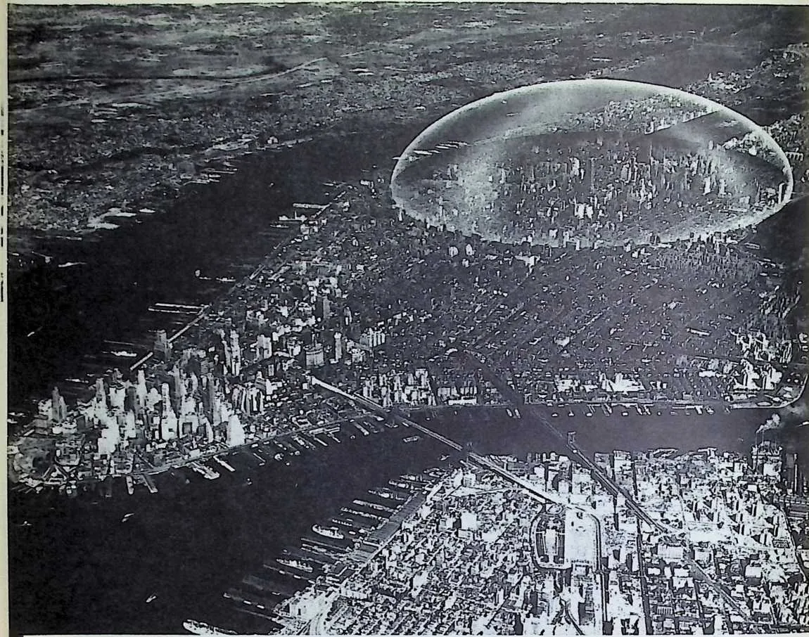
488 BIG GEODESIC DOME OVER MID-MANHATTAN
860The way the consumption curves are going in many of our big cities it is clear that we are running out of energy. Therefore it is important for our government to know if there are better ways of enclosing space in terms of material, time, and energy. If there are better ways society needs to know them.
861Domed cities can be illuminated by daylight without direct sunlight. That part of the dome through which the sun does not shine directly would be transparent. In summer the dome would be protected by polarized glass; during the sunny hours it would not. hold heat but in winter the sun would penetrate all the dome. The atmosphere will be dust-free.
862Controlling the environment through domes offers the enormous advantages of the extraversion of privacy and the introversion of the community.
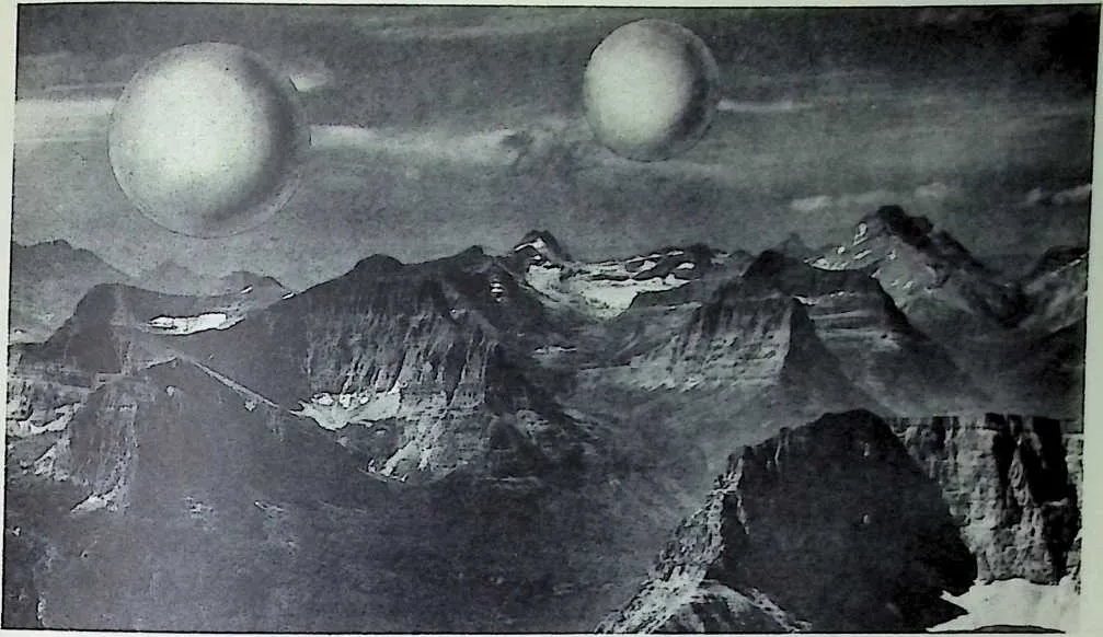
864489 A one hundred foot diameter geodesic sphere weighing three tons encloses seven tons of air. The air to structural weight ratio is ill. When we double the size so that geodesic sphere is loo feet in diameter the weight of the structure goes up to 7 tons while the weight of the air goes up to 56 tons—the air to structure ratio changes to 8/1. When we double the size again to a 400 feet geodesic sphere—the size of several geodesic domes now operating—the weight of the air inside goes to about 500 tons while the weight of the structure goes up to 15 tons. Air weight to structure weight ratio is now 33/1. When we get to a geodesic sphere one-half mile in diameter, the weight of the air enclosed is so great that the weight of the structure itself becomes of relatively negligible magnitude for the ratio is 1,000/1. When the sun shines on an open frame aluminum geodesic sphere of one-half mile diameter the sun penetrating through the frame and reflected from the concave far side, bounces back into the sphere and gradually heats the interior atmosphere to a mild degree. When the interior temperature of the sphere rises only one degree Fahrenheit, the weight of air pushed out of the sphere is greater than the weight of the spherical frame geodesic structure. This means that the total weight of the interior air, plus the weight of the structure, is much less than the surrounding atmosphere. This means that the total assemblage, of the geodesic sphere and its contained air, will have to float outwardly, into the sky, being displaced by the heavy atmosphere around it. When a great bank of mist lies in a valley in the morning and the sun shines upon it, the sun heats the air inside the bank of mist. The heated air expands and therefore pushes some of itself outside the mist bank. The total assembly of the mist bank weighs less than the atmosphere surrounding it and the mist bank floats aloft into the sky. Thus are clouds manufactured. As geodesic spheres get larger than one-half mile in diameter they become floatable cloud structures. If their surfaces were draped with outwardly hung polyethelene curtains to retard the rate at which air would come back in at night, the sphere and its internal atmosphere would continue to be so light as to remain aloft. Such sky-floating geodesic spheres may be designed to float at preferred altitudes of thousands of feet. The weight of human beings added to such prefabricated ‘‘cloud nines,’’ would be relatively negligible. Many thousands of passengers could be housed aboard one mile diameter and larger cloud structures. The passengers could come and go from cloud to cloud, or cloud to ground, as the clouds float around the earth or are anchored to mountain tops. While the building of such floating clouds is several decades hence, we may foresee that along with the floating tetrahedronal cities, air-deliverable skyscrapers, submarine islands, sub-dry surface dwellings, domed-over cities, flyable dwelling machines, rentable, autonomous-living, black boxes, that man may be able to converge and deploy around earth without its depletion.