1 Weight vs. Tension
1Beams will support a roof, and an easy way to support the beams is to put posts under them. One drawback is that the posts clutter up your floor space. You can line posts up and enclose them in a partition wall and pretend you wanted the wall there anyway, whether you did or not. What you can’t do, without recourse to clever engineering is free up floor space by moving the posts wide apart. If you do that, the beam starts to sag in the middle. If it sags too much, it breaks.
2 The limit in spacing posts is set by the material of the beam, as the builders of Stonehenge apparently understood (Diagram 1.1). If the crossbeam sags, its upper edge will be compressed, while its lower edge will grow longer. What counteracts the tendency to sag is chiefly the tensile strength (resistance to stretch) available along the lower edge of the beam. Stone is not notable for tensile strength, so the posts under simple stone beams must be closely spaced. Aqueducts or bridges can be made in this way, but the designer will soon discover that when the load they are meant to bear is added to the weight of the transverse members, the posts must be still more closely spaced. This wastes time and materials.
3 Roman engineers discovered a solution, the stone or masonry arch (Diagram 1.2). Though
domes had been built much earlier, we shall see that the Roman arch provides the first analytic
approach to dome engineering. The arch is essentially a device for dispensing with a center post,
by splitting the thrusts a center post would support and deflecting them to the sides. The
downward pull of gravity on the keystone is converted into paired outward thrusts, which the
face angles of successive stages transform into downward thrusts once more, but downward
thrusts now borne by the side columns. Thus the columns actually support the weight
of the keystone and its neighbors, without having to be located directly under the
stones whose weight they bear. So a central space is cleared beneath the arch. 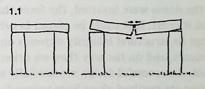
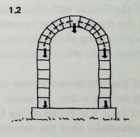
7 It is clear that everything is held in place by weight, so that the continuities of stress are chiefly compressive.
8 Two or more intersecting arches will define a dome-shaped space, again clear of supporters because the work of support has been transferred to peripheral columns. The beehive-shaped tombs at Mycenae can be analyzed in this way. There the tendency of such arches to collapse outward is countered by, in effect, burying the dome and relying on the weight of tons of earth to sustain outward thrust. For a similar reason the stone dome of the Pantheon in Rome is enclosed in a huge masonry cylinder.
9 Though the visible continuities are compressive, there is in fact an invisible tension network which analysis cannot ignore. Each component of a stone dome is held in place by the earth’s gravitational field, pulling tensionally ‘‘downward’’ through the structure. If the dome were inverted, the force that pulls it together would pull it apart. If it could be placed in orbit, it would drift apart. Thus its structural integrity depends on the weight of its components, and on the way they are oriented in earth’s gravitational field. A successful design is essentially a feat of balancing. All forces are resolved along lines perpendicular to earth’s surface, so that gravity and the mutual impenetrability of stones achieve a standoff. Any forces that deviate from this system of perpendicular resolutions will create a tendency to collapse inward or outward, and must be counteracted by braces or buttresses. Whether the placement of these is arrived at by rule of thumb, in the manner of the Gothic cathedral builders, or by sophisticated calculation in the manner of the twentieth-century engineer, their necessity says something about the precariousness of the struc-ture’s equilibrium, even when equilibrium is achieved without their aid.
10 If instead of discrete stones we use continuous curved beams of wood or metal for the arches, we arrive at the familiar ribbed domes of Saint Peter’s in Rome or the Capitol in Washington, but we do not substantially alter the structural analysis. We greatly reduce the super-incumbent weight, and we manage to separate the dome itself into ‘‘skin’’ (sheathing) and ‘‘bones’’ (truss work), but we are still relying on compressive continuities to sustain most of the load. In certain respects, the efficiencies are less rational than in a stone dome: since the zenith of the arch no longer serves as a keystone, its chief function now is to load its supporters irrelevantly. The greatest concentration of structural members is at the zenith, where they have nothing to support, but instead constitute a problem for the members that support them. And successful design is still a feat of balancing. Unless thrusts are perpendicularly resolved, the dome will still tend to collapse inward or burst outward. Design usually elects to err in the latter direction, and the downward thrust at the zenith is translated into an outward thrust around the periphery (precisely where the structural members that ought to cope with it are most widely spaced). Here, in place of stone buttresses, a peripheral clamping ring holds things together. At Saint Peter’s the system for coping with peripheral outward thrusts is reinforced by a huge iron chain which has kept the dome intact for four hundred years.
11 The Saint Peter’s chain is a multi-toned Band-Aid applied to a region of potential failure. A structure of almost any configuration can be designed on this principle: put it together somehow, and reinforce failure points as they appear. Failure points appear because portions of the structure impose an undue load on other portions: the load distribution is irregular and only accidentally related to stress-bearing capacity.
12 It is possible, however, to take a completely different approach.
13 The way to do this is to abandon altogether the concept of structural weight impinging on the compressive continuity of bearing members, the whole guarded by occasional tensional reinforcement. Instead of thinking of weight and support, we may conceive the domical space enclosure as a system of equilibrated omnidirectional stresses. Such a structure will not be supported. It will be pulled outward into sphericity by inherent tensional forces which its geometry also serves to restrain. Gravitation will be largely irrelevant.
14 In a soap bubble or a balloon, an envelope of surface tension attempts to close inward against the outward compressive force of the enclosed air. The equilibrium between tension and compression is modeled as a spherical shape. In a hollow spherical structure, of which a dome is a section, the compressive forces, like the tensile, are incorporated into the skin itself, and their direction cannot be divided in so obvious a way between inward-tending and outward-tending. The tensile web supports the compressive members, and is also supported by it. The tensile pull can be as easily imagined tending outward as inward.
15 To understand this bootstrap effect, consider first a primitive tensile structure, consisting of two trees, a clothesline, and two poles (Diagram 1.3). The poles slant in opposite directions, and 1.3 the system sketches a contained space.
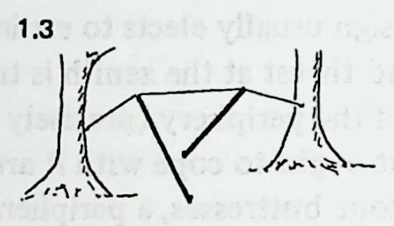
17 Next, discard the trees, and fix the ends of the line to the earth, slanting the poles so that their lower ends and the anchor points of the line define a quadrilateral (Diagram 1.4 1.4). Provided the poles are prevented from slipping, this is perfectly stable, and we have framed a tent with no center pole.
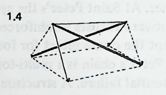
19 If we join the rope anchor points by a third pole, and replace the dotted lines on Diagram 1.4 with additional rope (Diagram 1.5), we shall find that we have a self-sufficient tension/compression system. The rope holds the poles both together and apart. The poles in turn lend shape to the prism-shaped rope network.
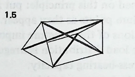
21Here the reader should convince himself of the properties of this structure by experimenting with a simple model. Three dowels of convenient length (say, 9 inches) will do for the poles. Drive nails or pins into their ends and then tie them together as shown in Diagram 1.5, making the strings two-thirds the length of the dowels. As the last string is tightened, the tension network can be seen pulling the system outward into taut equilibrium. Thereafter the system resists deformation, and if deformed to an extent permitted by the elasticity of the tendons, will tend to restore itself to equilibrium.
22 The vertex points of this system, 6 in number, may be imagined as points on the surface of an enveloping sphere, since they are equidistant from a point in the center of the tensile prism. Additional members (poles and ropes, or struts and strings) can be so placed as to increase the degree of approximation to a sphere: we can make the system as spherical as we like. (This will be discussed in detail later.) As we do so, we shall find that the poles sketch the sphere’s inner surface, the ropes its outer. In like manner, the stresses on the outer skin of a spherical structure tend to be tensile, and the stresses on its inner skin compressive. And the integrity of the spherical skin as a whole is wholly independent of central support. It is also independent of compressive load-bearing of the kind exemplified in post-and-beam construction or in the arch, since the compressive members are not in contact.
23 Now, return to the transition between Diagram 1.4 and Diagram 1.5 and note that structural integrity requires either a complete rope-and-pole system or else a partial system plus the earth. Tensional circuits must be completed somehow. Motion pictures of air-lifted geodesic domes show the bottom-edge weaving and wavering until it is set on the ground and affixed there by fastenings.
24 The rope-and-pole prism shown in Diagram 1.5 is the simplest Tensegrity structure. (Tensegrity = Tensional integrity.) It has no redundant components. All the domes described in this book, notably the numerous ‘‘geodesic’’ variants, exemplify special cases of Tensegrity principles. Their salient continuities are tensional, and their upper portions are not so much supported as lifted by tensional forces.
25 Unlike the stone arch or the stone dome, such structures are not made stronger by being made heavier. In fact, they can with advantage be made negligibly light in comparison with the tensional forces that bind the components. The one-way tension of terrestrial gravity is replaced by the multi-direction tension of structural members. The system is therefore stable in any position.
26 Moreover, a tendency to peripheral or local stresses, such as those restrained by the chain round the dome of Saint Peter’s, is supplanted by a multi-directional stress equilibrium. A corresponding multi-directional tension network encloses accidental stresses wherever they arise. There are no points of local weakness inherent in the system.
1.1 Appendix to Chapter 1: Tensegrity Prisms
27We have noted that the structure developed in Diagram 1.5 is the simplest Tensegrity, consisting of 3 compressive struts and 9 tensile tendons (tendon = the portion of the tensile network between the two adjacent strut ends). It resembles a triangular prism, one end of which has been rotated with respect to the other, thus twisting the quadrilateral sides. One additional strut (Diagram 1.6 1.6) will
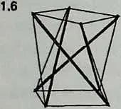
29 convert the end triangles into squares; a further strut
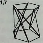
31 (Diagram 1.7) will convert them into pentagons; and so forth. It is possible in this way to generate a potentially infinite family of T-prisms corresponding to the prisms of solid geometry.
32 We may imagine any such T-prism enclosed in a cylinder of height and diameter . The tendons (of length ) outlining the end -gons are called end tendons. There are also side tendons, of length . (In general denotes the number of struts, the number of side tendons, and the number of tendons bounding the end polygons.)
33 We shall assume that the end -gons are equilateral. If they are equal to one another, the prism is uniform. If they are unequal (though equilateral) the prism is semi-uniform, and would be enclosed by a truncated cone instead of by a cylinder.
34 Though they join corresponding vertices of the top and bottom -gons, the struts of any T-prism all lean uniformly, either clockwise or counterclockwise. That is because of the twist referred to above; the top polygon has been rotated with respect to the bottom polygon through an angle called the twist angle (Diagram 1.8). Whatever the height or
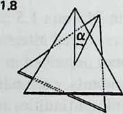
36 diameter of the structure, it can be shown that for a given number of struts, the twist angle is constant and is given by the formula
| (1.1) |
37 This remarkable fact1 makes it easy to calculate the lengths of struts and tendons for any values of , , and .
38 One way to prove the twist-angle theorem is to use cylindrical coordinates. Diagram 1.9 1.9 shows the coordinate frame with 1 strut , 1 side tendon , and 1 end tendon . Since the end tendon is one edge of the end -gon, it subtends a center angle of . The cylindrical coordinates () of and are thus and , respectively. Point is not located above point but is displaced counterclockwise by an additional angle , the twist angle; its coordinates are .
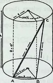
40 The distances and are strut length and side tendon length , respectively. The standard distance formula for cylindrical coordinates gives:
41 and
42 Rearranging the first equation, we obtain
43 and substituting this for in the second equation gives
44 To find out how this varies, we differentiate it, obtaining
45 This is messy, but take heart. When the system is taut the tendon length will be minimal, and the derivative above will , signifying no rate of change . At this point the denominator drops out, since it must be the numerator that equals zero. And since the product of the radii cannot be zero, it can only be the functions of that have vanished. So at the equilibrium state,
46 which is possible if
47 whence
48 and
49 The twist angle therefore is a function of alone, and is given by Equation 1.1, above. If we now disregard such physical inconveniences as tendon stretch and deformations imposed by the weight of the structural members, we can use the cylindrical coordinate distance formula to calculate the dimensions of an idealized semi-uniform T-prism. Putting for —that is, one-half the diameter—we get:
| (1.2) |
| (1.3) |
| (1.4) |
50 If the T-prism is semi-uniform there will of course be two end tendon lengths, corresponding to the two diameters.
51Example 1Semi-uniform T-prism, 12 inches high, end diameters 6 inches and 10 inches: 5 struts. The equations give 14-inch struts, 12.7-inch side tendons, 3.5-inch tendons for the smaller end, 5.9-inch tendons for the larger end.
52Example 2Uniform T-prism, 3 struts, and as high as it is broad. (Thus ): End tendons are sin 60° or 0.86603; struts are 1.39, side tendons are 1.03. Thus for a model 12 inches high, end tendons would be 10.4 inches long, struts 16.7 inches, side tendons 12.4 inches.
53 It may occur to us to want all tendons equal. In that case we put the right side of Equation 1.4 equal to the right side of Equation 1.3 and rearrange to give : for ,
| (1.5) |
54 This proves to be solvable for . For it yields 0, (that is, no height at all), and for it yields a function of , which is not modelable. Thus, while there is an infinite number of regular prisms, there are only three regular T-prisms, corresponding to . ( and are structurally meaningless). Their proportions are: