16 Space Frames
1Very large domes keep the lengths of their members within bounds by using very large frequencies; as we shall soon see, a has been constructed. But very large frequencies engender chord factors that are very much alike; two typical values for a are 0.033004 and 0.031676; for a 100-foot radius the members corresponding to these differ in length by less than inches (about 4 percent). But zero difference in length is the formula for flatness, so any vertex in a dome of this frequency is getting nearly flat. The tension system is losing mechanical advantage, and a little stretch here and there (elasticity of materials; inaccuracy of construction; play of joints) would permit a vertex to pop inward under load.
2 At how low a frequency this problem becomes important depends on materials and tolerances, but it is probably wise to be wary of anything above or .
3 Being wary means imparting a third dimension to the frame. The frames we have been discussing are (mathematically) of zero thickness: though wood or metal has a third dimension, the diagrams we have had wood and metal follow consist of widthless lines running from point to point. Thickness entails a second line closer to system center than the first. There are several ways of doing this elegantly and without redundant weight. All of them are reducible, essentially, to a pair of frames, outer and inner, trussed together.
16.1 Diamond Patterns
4One especially elegant method, in use since at least 1960, is to make the skin integral with the trussing system. This is the principle of Fuller’s patent on Laminar Geodesic Domes. It is based on the simple fact that the same set of points can be joined in two different ways to combine, in effect, two different breakdown systems. Diagram 16.1 shows the principle: instead of joining points to make two triangles, and , we omit the connection and instead join toD. The connections follow a Class II breakdown, the others a Class I with a few members omitted. It could all be done with struts, though hub details would get complex; Fuller’s solution was to insert a creased diamond as shown.
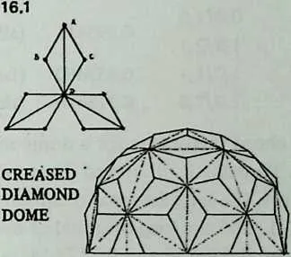
6 By building the entire dome in this way we can eliminate the strutted frame entirely and allow the joined edges of diamonds and the creases down the centers of the diamonds to take its place. Such a dome has in effect a single circumsphere, passing through all vertices, but two different in spheres, the and the 2v, the difference between the radii of the latter is the virtual thickness we have conferred.
7 The diamond geometry is independent of dual radii. It was first worked out in the early 1950s, for a structure erected in Woods Hole, Massachusetts, and is interesting because it permits a structure with two diamond diagonals but only one edge length.1
8 Diagram 16.2 shows how. We want to make 0,0/1,0 equal to 1,0/2,1. We commence by noting that if 2,1 (the centroid of the icosa face) has coordinates 0, 0 while 1,0 has coordinates then the distance 0,0/1,0 will be (by Equation 9.2):
9 and the distance 1,0/2,1 will be:
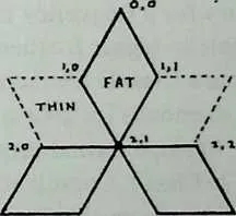
11 From the Class I table (Chapter 20) we learn that the coordinates of 2,1, the centroid of the icosa face triangle, are 36, 37.3773681. We insert these values for 0 and 0, equate the two expressions with one another, and solve this equation for , which proves to be .
12 From this we derive a icosa breakdown using only 3 chord factors:
13 0,0/1,0
14 1,0/2,1
15 1,0/1,1
16 1,0/2,0
17 0.393411
18 0.453480
19 0.313800
20 (all diamond edges)
21 (fat-diamond diagonal)
22 (thin-diamond diagonal)
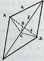
24 These chord factors are for a dome made in the usual way, out of struts. To make it of creased diamonds, we need two more distances, the long diagonal common to every fat diamond (0,0/2,1) and the long diagonal of every thin diamond (2,1/4,2). These are 0.640852 and 0.713644, respectively.
25 A little experimenting with cardboard diamonds will show that once the edges are correctly cut, the angles of crease are self-adjusting. For stiffer material, for instance, sheet metal creased in a brake, we would want to know the crease angles in advance. As Diagram 16.3 shows, they are easily calculated: 166.8° for the fat diamond, 142.52° for the thin.
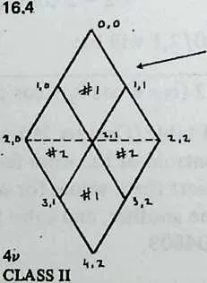
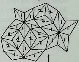
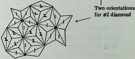
26 If we make a cardboard model, or even fit just a few cardboard diamonds together, we can easily see that, whereas the material is thin, the geometry of the shell confers virtual thickness, interesting but unnecessary for a frequency this low. The easiest way to extend the principle to higher frequencies where it can be of some use is to work from a Class II breakdown. Diagram 16.4 shows the derivation of the diamonds for a and Diagram 16.5 shows how they fit together. Again, a second breakdown has appeared: the creases outline a Class I. Coordinates need not be tampered with, but simply taken from the Class II table (Chapter 21 or Chapter 23). Again two diamonds suffice.
27 It should now be clear how higher frequencies would be dealt with. Make a Class II breakdown diagram; mark symmetries (that is, equal chord factors: colored pencils are useful); outline the diamonds; calculate the necessary chord factors, remembering to include the long diagonal of each diamond. If the crease angle is needed, obtain it as shown in Diagram 16.3. The creases will follow a Class I breakdown at half the chosen frequency.
28 Both of the Class II breakdown methods discussed in this book yield two diamonds at . At higher frequencies Method 3 displays its usual economies, the number of different diamonds being just half the frequency count (four for , eight for ). Method 1 requires six diamonds for and twenty for , the number of different components, as usual, increasing rapidly.
16.2 Trussed Frames
29The other principal method of lending stiffness to a shell of high frequency (low local curvature) is to use an outer frame and an inner frame and truss them together.
30 The American Society for Metals (ASM) dome in Cleveland (Popko, figures 69--72) consists of two shells of identical geometry, each Class II, the radius of the inner one 30 inches less than the radius of the outer, joined together at the vertex points by 30-inch radials. How something like this could be designed is obvious: two sets of strut lengths are figured, using the same chord factors but two slightly different radii.
31 To save weight (and lend grace) numerous struts are omitted, leaving a pattern of hexagons which are then stabilized tensionally, the tension cables replacing the omitted struts (Popko, figure 71, shows connector details).
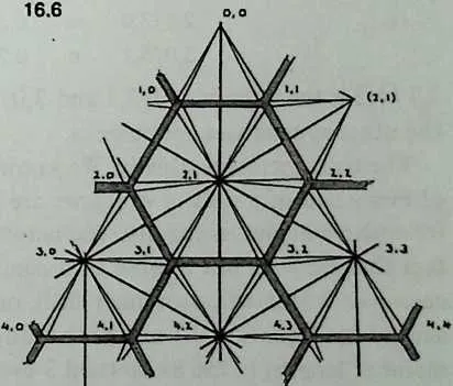
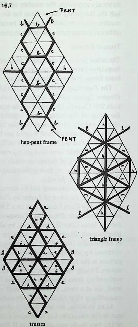
32 Or the two shells need not be identical. The Montreal Expo ‘67 dome, a tour de force of design by Fuller and Sadao Inc., in effect trusses a Class I outer grid to a Class II inner grid. As we learned from our discussion of diamonds, both classes can be derived from Class II coordinates by choosing different points to interconnect. Diagram 16.6 shows the principle, using a lower pair of frequencies ( and ). The hexagon pattern is the inner shell, obtained by joining selected Class II vertices. The triangle pattern is the outer shell, obtained by joining vertex pairs as shown. Finally the missing struts in the hex-pattern inner shell are replaced by truss members which rise from the hex corners to meet, six at a time, at the outer shell vertices. The result is an exceedingly rigid space frame, virtually a spherical octet truss.
33 As an exercise, we may quickly obtain every member length in our example. Let us assume a ratio of 100/95 for the radii of the two shells and select Class II Method 3 for its characteristic economies. We first see which chord factors we need; Diagram 16.7 shows that the hex and pent boundaries use only 3 lengths, b, c, and h. We extract these directly from the table in Chapter 23, and because this shell will have a radius of 0.95 we take 95 percent of the result:
3536 Class II Method 3
37(r = 0.95)
381,0/1,1 0.189484
391,0/2,0 0.158653
404,0/4,1 0.160239
41 We next obtain chord factors for the outer shell’s triangulation, using Equation 9.2 and the coordinates from the table. This shell has a radius of 1, so the chord factors are written down exactly as they come from the calculator. (Just one detail: the strut from 2,1 which crosses the Class II triangle’s edge goes to in the next Class II triangle. This point has the same as 2,1 in the table, but its 0 will be 72° higher—108 instead of 36.) Only four values occur, and if our understanding of Class II Method 3 symmetry was insufficient to tell us this, we should soon find it out by experiment.
42434v Class I (r = 1.0)
440,012,1 k 0.275904
452,112,1 I 0.321244
462,113,0 m 0.314751
473,0/5,1 0.264769
48 2,1 /4,2 is the same as 0,0/2,1 and 3,0/4,2 is the same as 2,1 /3,0; the other symmetries are obvious.
49 The truss members, finally. We know the spherical coordinates of every pair of points in which we are interested, and the standard formulae will give us the distance between them, regardless of the fact that they are not located on a common sphere. One point of each pair is located on an inner shell, one point on an outer. We simply use Equation 9.1 and both radii, 1.0 and 0.95. Of the eight member lengths in the Method 3 breakdown, hex and pent edges have already accounted for three; the trusses correspond to the other five.
51 truss members = 1, r2 = 0.95)
520,0/1,0 | 540.173343 | |
552,0/2,! | 570.197168 | |
582,0/3,0 | 600.164721 | |
613,0/3,1 | 630.187039 | |
643,0/4,0 | 660.157577 | |
67 These are used exactly like chord factors: we multiply by the radius of the outer shell to get the actual lengths of truss members. The lengths of inside shell members are also obtained by using the outside shell radius, the correction having been already built into the chord factors.
68 This very intricate two-shell trussed domical space frame uses members of just twelve different lengths. It’s not a backyard project. The hubs would need careful study. Each hub on the outer shell receives twelve members, each hub on the inner shell six. Hub design would need angles which Chapter 17 tells how to obtain.