3 Complex Spherical Tensegrities
1The simplest spherical Tensegrity, the six-strut Valence-4 version with struts in three parallel pairs, has occupied us for many pages. There are several reasons for understanding it in considerable detail. (1) Tensegrity structures and the geodesic domes of which they supply first-approximation stress diagrams, have been shunned by many investigators as unduly mystifying. It is worthwhile becoming convinced that their behavior yields to rational analysis. (2) While dodges such as calculus would have shortened the work, they can mislead unless we are sure we understand the phenomena we are using them to describe. Simple mathematics and experience of the directions in which strings pull taut will suffice if we are patient. (3) The analysis has turned up some principles that will help us with more complex structures. These include:
- the property of behaving as a system in response to local events,
- the normal state as an ideal equilibrium about which observable behaviors oscillate,
- elasticity multiplication, a special case of synergy,
- the parabolic curve as a graph of system behavior,
- the value of the dip angle as a point of analytic attention.
3.1 Great Circle Tensegrities
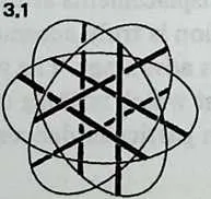
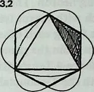
2Examining the symmetries of the six-strut Tensegrity, we may think of surrounding it by three intersecting hoops, located like the equator, the Greenwich meridian, and the 180° meridian (Diagram 3.1 3.1). Each of these hoops—a great circle, or geodesic—passes through both ends of one pair of parallel struts, and the three of them contain the system symmetrically. They resemble the great circles of the regular octahedron (Diagram 3.2 3.2), each of which contains four octahedron edges. We may wonder if there are Valence-4 Tensegrity equivalents to other great-circle polyhedra. There are; but their number is severely restricted.
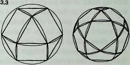
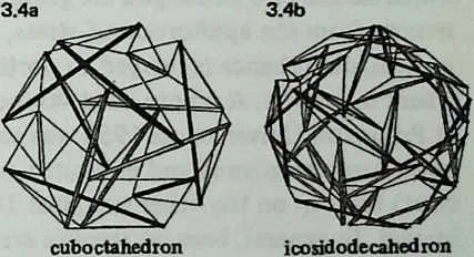
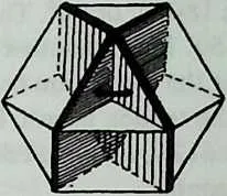
5 Still, they have a great deal to teach us. We need polyhedra whose edges, projected onto a sphere, make great circles. We also need exactly four edges at each polyhedron vertex. There are just two polyhedra that will fulfill these conditions: the cuboctahedron and the icosidodecahedron (Diagram 3.3 3.3). Tensegrity equivalents to these polyhedra are shown in Diagram 3.4.
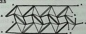
7Once again, make models: preferably of both structures, but at least of the simpler (cuboctahedron). It is worth a little trouble. The Tensegrity cuboctahedron (abbreviated T-cuboctahedron has twelve struts, arranged in four groups of three. Paint each group a different color before assembly. Use 1/4-inch or 3/16-inch dowel and make the struts 12 inches long. Drive pins into the dowel ends to anchor the tendons. Use thin, tough cordage: braided nylon fishline is excellent. (Avoid monofilament nylon, in which it is difficult to tie a nonslipping knot.) Diagram 3.5 shows a net diagram, and tendon lengths are indicated. Do as much as possible flat on the table; then join the indicated points, to close up the sphere.
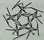
8Diagram 3.6 shows part of the net diagram for the T-icosidodecahedron. It uses thirty struts in six groups of five (six colors).
9The T-cuboctahedron when completed should contain four equatorial triangles; the T-icosidodecahedron should contain six equatorial pentagons.
10 The T-cuboctahedron resembles the regular cuboctahedron in two principal ways. (1) Its struts describe four symmetrically placed great circles. (2) Its tendons outline the six squares and eight triangles of the cuboctahedron’s faces.
11 We immediately notice two points of difference. (1) Whereas the cuboctahedron has six edges around each great circle, the T-cuboctahedron has only three struts. (2) The square and triangular faces outlined by the tendons do not abut on one another as do the faces of the polyhedron. They are separated by diamond-shaped segments, each with a strut lying along its long axis and with two other struts facing each other end-to-end across its short axis. These differences from the parent polyhedron are general characteristics of Valence-4 Tensegrities.
13 Experimenting with the T-cuboctahedron, we may collect some observations about its behavior under stress. We remember a striking habit of the six-strut Tensegrity: when we grasped two struts that lay in the same plane and moved them together or apart, the other pairs of struts behaved in exact concert. Will this still work? Not quite. In the T-cuboctahedron, two struts in the same plane will be adjacent sides of a circumferential strut triangle. If we grasp and wriggle two of these, action will occur throughout the system, but not uniformly. Watch the gaps between adjacent strut ends of the circumferential triangles. These will open and close as struts displace themselves. The gaps within which lie the two struts you are grasping will barely alter. Others, remote from the application of stress, open and close markedly. In general, disturbance is relayed to portions of the system far from where it entered. A ninety-strut 40-foot Tensegrity sphere erected at Princeton University in 1953 was struck by a snowplow at a point near the ground and exhibited component failure (a bent strut) high up on the other side, just 180° from the point of impact. In general, because stresses are diffused, component failure is rare. Light models of wood and string that look as though a cat could demolish them can be kicked, bounced, thrown, even accidentally stepped on, without damage.
14 If a model is stood on one of its triangular sides, another equivalent triangle will be uppermost. Lay a weight—a heavy book—on this upper face. As the model compresses, it will rotate. The equatorial strut triangle neither bulges nor shrinks; it simply revolves. Others are deformed in complex ways. The net effect is compression of the sphere into an oblate spheroid, but without increase in diameter. The rotation of the equator takes up the forces that might be expected to expand it.
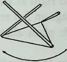
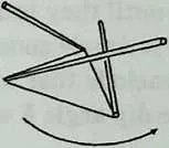
16 The direction of rotation Under contractive stress is determined by the handedness of the system. Most Tensegrity systems exist as right- and left-handed mirror pairs; a particular model is either one or the other. It is easy to see (Diagram 3.7) that the three struts 3.7 which rise from vertices of a triangular base can sketch either a clockwise or a counterclockwise rotation. Under compressive stress, these struts swing away from one another, either clockwise or counter-clockwise, according to the handedness of the system. The three struts angling downward from a triangular summit also swing away from each other, but since the upper cone is inverted with respect to the lower, their movement with respect to the equator is in the opposite direction from that of the base struts. Thus each equatorial strut is pulled both clockwise and counter-clockwise simultaneously; the stresses cancel, and the equatorial struts move neither out nor in. Thus the size of the equator (as we have noticed already) is unchanged. Instead the equator, and with it the whole system, is carried bodily around in the direction of rotation of the base struts. The only motionless zone is the base triangle, which is fixed to the floor, the tabletop, or the earth.
17 The six-strut Tensegrity of Chapter 2 is an exception to the general principle of right- and left-handedness. It has no handedness, hence no ring of cancellation, and so behaves with perfect symmetry throughout. All twelve of its vertices are displaced alike.
3.2 Dip-Angle Calculations
18We next require a general procedure for calculating the dimensions and component lengths of spherical Tensegrities more complex than the six-strut one we have analyzed. The key to this, as before, is the dip angle.
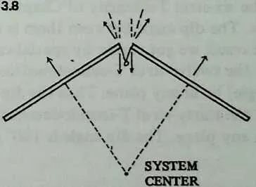
20 Examining the six-strut structure in Chapter 2, we discovered that the dip angle between parallel struts was necessarily 90°. Diagram 3.8 3.4 shows how to extend this reasoning. It depends on something we can readily observe by inspecting a model, that any strut we may concentrate on is staying where it is because two opposed forces are balanced out. The two tensile planes at whose intersection it lies are bounded by four tendons whose net effort is to pull it straight outward, away from the center of the system. It is anchored at its ends, however, by tendons whose net effect is to pull it straight inward, toward the center of the system. These forces can be diagrammed right at the end of the strut, where all tendons are attached; Diagram 3.8 3.4 represents them by light arrows. The tendons in the tensile plane align themselves midway between these forces.
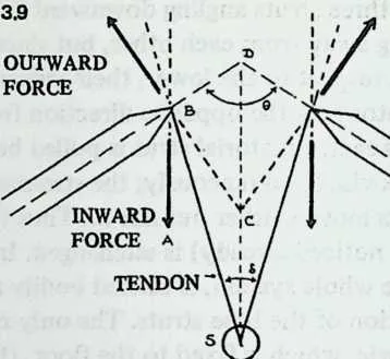
21 Diagram 3.9 ?? shows how the situation would look if the struts were extended until they touched. They enclose an angle we may call 0. The rest is simple geometrical reasoning, shown with the diagram. We conclude that whatever the angle, at which two struts meet, the dip angle will be
| (3.1) |
22 These two struts are sides of a regular polygon which lies in the plane of a great circle round the models we have examined, but which may lie in a lesser circle plane round Tensegrities we shall encounter later. In either case, the angle between two adjacent struts is the interior angle between any two sides of a regular polygon with sides. This is . Equation 3.1 tells us that the dip angle is 90° minus half this, or . Simplified, this gives us a compact alternative form for the dip-angle equation:
| (3.2) |
24 So we have only to divide 180° by the number of struts in one plane of a Tensegrity sphere (otherwise put, the number of struts round a great circle or lesser circle) to obtain the dip angle between any two of these struts. The six-strut Tensegrity of Chapter 2 has two struts in each plane. The dip angle between them is thus 180°/2, or 90°, the same result we got earlier by special-case reasoning. In the twelve-strut T-cuboctahedron, three struts (an equilateral triangle) lie in any plane. Thus the dip angle is 180°/3, or 60°. In the thirty-strut T-icosidodecahedron, five struts (a pentagon) lie in any plane. The dip angle is 180°/5, or 36°.
3.3 Calculation of Remaining Dimensions
25We shall now see how the dip angle can be used to calculate all the remaining dimensions of a Valence-4 Tensegrity sphere.
26 It is convenient to call the strut length 1 and express all other dimensions in strut lengths. If calculation shows that a certain tendon length is 0.523, this means it is strut length. If we are using 8-foot struts, this tendon will be , or 4.184 feet or 50.2 inches.
27 For model-building, we normally start with known strut lengths, anyhow. For larger structures, we are more likely to start with a desired diameter. No problem. Equation 3.5, below, relates radius to strut length and so gives us access to all the other dimensions, even when the size of the structure we want to build and its geometry are the only two things we know. Proofs of all equations in this chapter are given in the chapter appendix. Elementary geometry and trigonometry suffice to yield all of them.
- (1)
- We obtain dip angle
(3.3) 28where = number of coplanar struts around the structure.
- (2)
- We derive the gap .
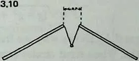
The gap (Diagram 3.10) is the linear
29distance between the ends of two adjacent struts on a greater or lesser circle.
(3.4) - (3)
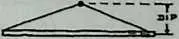
- We next find the dip. The dip is the median of a tensile plane: the distance (Diagram 3.10)
from a strut end to the mid-point of the strut that crosses beneath it. Its symbol is ,
and
(3.5) 31We pause to notice that tendons which simply follow the dip, joining the ends of adjacent struts to the midpoint of the strut passing below, will suffice to make a stable structure with no othertendons whatever. In these center-connected Tensegrities, whose only tension members are little V-shaped slings, the tension network is no longer optically continuous but must be traced in part through the struts. This is not a recommended method of construction because it imposes a bending load on the struts. It is a good way to analyze certain features ofTensegrity construction. It particular, it draws our attention to the fact that the dip is the crucial parameter. When the dip slings in such a model are correctly dimensioned, the gaps and strut angles will automatically adjust themselves into the equilibrium state, and all struts around any great circle or lesser circle will align themselves in a common plane.
- (4)
- We now obtain the radius, .
This means the radius of the circumsphere: a sphere into which the Tensegrity would
exactly fit, all its strut ends touching the spherical envelope. Or it is the distance outward
from the center of the system to the end of any strut. The equation is brief:
(3.6) 32This gives us the radius expressed in strut lengths. Should we wish to design a sphere of given radius , then the strut length is, of course, .
- (5)
- Our next step is to obtain an arbitrary quantity .
Its whole purpose is to simplify the tendon-length equations by working out separately a
portion common to each of them.
(3.7) - (6)
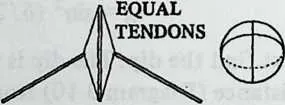
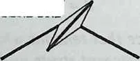
- Diagram 3.11 shows why we frequently need two different tendon lengths. When strut circles
cross one another at 90° angles, tendon lengths are equal. When they cross at some other angle,
long and short tendons alternate around each strut. To find the two lengths, we shall need the
angle
at which the planes bounded by strut circles cut one another: more precisely, we need
the cosine of this angle. The axes of great-circle and lesser-circle planes are a
polyhedron’s axes of symmetry, and since all regular and semi-regular polyhedra have
either octet or icosahedral symmetry, there are only three possible values for :
- Circle axes at 90°.
- Octahedral symmetry, circle axes at .
- Icosahedral symmetry, circle axes at .
34Diagram 3.12 shows the simple case of the cuboctahedron. It is 3.12 octahedrally symmetrical, and we may expect cos t to be 1/3. That is because the angle at which great-circle planes intersect is the dihedral angle of a tetrahedron, or 70.5288°, the cosine of which is 1/3. Tendons calculated by using this value in Equation 3.7 and Equation 3.8, below, will be taut and the model symmetrical, with circumferential struts aligned in common planes.
35We pause to note one complication, more likely to affect the model-builder than the dome engineer: the essentially static mathematics of polyhedra will not always coincide with the dynamics of a Tensegrity. This is apt to show up whenever we encounter edges that lack a triangular face on at least one side. For instance, the small rhombicosidodecahedron, a Valence-4 polyhedron, consists wholly of intersecting lesser circles which cut it into square, pentagonal, and triangular faces. It yields a handsome Tensegrity sphere of sixty struts. Since the twelve lesser circles are icosahedrally coordinated, is , and Equation 3.7 and Equation 3.8 will yield long and short tendon lengths. If we construct the model, however, we shall find (Diagram 3.13) that each strut has a triangular face along one side of only one end. The triangle pulls the associated square face into a diamond shape in such a way as to make all strut intersections equiangular. To make the model symmetrical we must refigure the tendons as though were 0, and all tendons of equal length. Methods of foreseeing such effects are of such limited application as not to seem worth the space required to expound them. Check all Tensegrity predictions by building models.
- (7)
- We may now figure the long and short tendons, and .
(3.8) (3.9) 36When the great-circle axes cross at , we have a single tendon length , obtained very simply:
(3.10)

37To illustrate this latter situation, consider the six-strut Tensegrity of Chapter 2. It has two struts in each plane, so by Equation 3.2 the dip angle is 180/2, or 90°. The gap, by Equation 3.3, is , or 0.50. This is another way of stating what we learned before, that the separation between parallel struts is half a strut length. And the tendon length, by Equation 3.9, is (0.5 + l)/4, or 0.6124, which checks with what we obtained by geometrical reasoning. Table 3.1 illustrates the other two symmetry cases, deriving step by step the dimensions given in Diagram 3.5 and Diagram 3.6 for the T-cuboctahedron and the T-icosidodecahedron. A sophisticated pocket calculator makes such computations so simple it is easy to become addicted to their multidecimal precision. Pause to reflect what it is we are calculating. We are describing to a high degree of accuracy the equilibrium state of an ideal Tensegrity sphere built of weightless materials. In the equilibrium state so envisaged, the tendon network pulls only against the ideal incompressibility of the compressive struts. In a real structure the one-directional tensile field of earth’s gravity pulls through the multidirectional tensile field of the structure, imposing flattenings and compensatory rotations, as described earlier in this chapter. Tendons, however tightened, will describe catenaries, not straight lines, and two tendons will not meet at a point but at a fastening of measurable size. Moreover, no one but a model-builder or a sculptor is likely to construct a complete sphere. Tensegrity domes are quite practical, and inspection of spherical models will suggest the simplicity of equatorial truncation. Groundlevel anchor points for certain tendons, and the thrust angles of half-struts embedded in the ground, are easily determined. Since with the aid of a few strategically placed turnbuckles it is relatively easy to lengthen or shorten tendons in the field, the designer may safely calculate dimensions from the equations, compensating where necessary for modes of fastening, and make adjustments on the actual structure.
| T-Cuboctahedron | T-Icosidodecahedron | |
| 3 struts per great circle | 5 struts per great circle | |
| Dip angle | ||
| Gap | ||
| Dip | ||
| Radius | ||
| Long tendon | ||
| Short tendon | ||
| Thus, a model using 12-inch struts would require tendon lengths of 18.2 cm. and 15.7 cm. and would have a radius of 7.9 inches.1 | Thus, a model using 12-inch struts would require tendon lengths of 16.6 cm. and 15.3 cm. and would have a radius of 11.3 inches. | |
| A 10-foot-diameter structure (radius 5 feet) would have struts feet long and use tendons 54 inches and 46.8 inches long. | A 20-foot-diameter structure (radius 10 feet) would have struts 10.89 feet long and use tendons 71 inches and 65.6 inches long. |
3.4 Appendix to Chapter 3: Derivation of Tensegrity-Sphere Equations
38Why the dip angle assumes the value it does, we have discussed in the text. This appendix shows in detail why the gap, dip, radius, and tendon lengths necessarily follow from the dip angle. The reader who is content simply to use the equations is at liberty to skip these proofs.
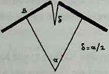
39 Diagram 3.14 shows two struts, with tendons at the ends making a dip angle , and radii from their centers to the center of the system, where they make the center angle . Since all the center angles in the system will total 360°, for . But from Equation 3.2, .
41 We move on to Diagram 3.15, which shows half a strut , two radiiBO and with the angle between them, a half dip angle, , and a half gap, . Angle and Angle are both 90°, and is the dip.
42 We have shown that ; hence Angle , and Angle . Since , triangle is isosceles, and Angle . But since Angle , Angle , which is a straight line minus both Angle and Angle , must be 90°. Thus is a right-angled triangle, and . Calling a strut length 1, . But since Angle , and Angle = Angle = (180° - δ)/2, Angle . Thus:
| (3.11) |
43The gap equation follows readily. is half the gap, and Angle is 90°. So in the right-angled triangle , where the angle at is , . Thus the , or , which simplifies to
| (3.12) |
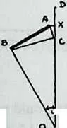
45 To derive the radius, we redraw the previous diagram (as Diagram 3.16) inserting ()
the circumsphere radius we wish to find. It is the distance from the center
to the tip of a strut. Various things we know already are written beside
the diagram. We see immediately that in the right-angled triangle , Side . We also see that in
the isosceles triangle ,
Side . Thus . Finally, in
right-angled Triangle ,
the hypotenuse .
Substituting into this the value we have just obtained for , we
get .
Since
and ,
this reduces to 3.16 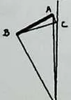
| (3.13) |
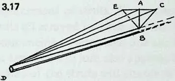
46 Diagram 3.17 and Diagram 3.18 show how the equations for the tendon lengths are derived. Diagram 3.17 is a perspective drawing showing half a strut, the gap, the associated dips, and the two tendons. We have also drawn a perpendicular, , from the strut to the midpoint of the gap (thus ) and joined to .
47 The working is now fairly obvious. In right-angled Triangle , we know and and can calculate . In the right-angled Triangle , we know that , and having derived can calculate . This is the quantity of Equation 3.6.
48 We then turn to Diagram 3.18, in which and are each and . In Triangle we thus know two sides and the cosine of the included angle, and the standard formula yields us Equation 3.8 for the short tendon . The equation for the long tendon is then derived from the fact that .