6 Rigid Tensegrities
1We are now ready to make the transition from Tensegrity structures to geodesic domes. We commence by noticing that the polyhedra we have been generating with the aid of frequency subdivision have one particularly useful property. As the frequency of subdivision increases and the number of edges grows more numerous, the surface of the sphere-like form also grows smoother.
2 Analogously, in Tensegrity spheres, gaps and dips grow less and less obtrusive. We shall now see how this fact can be put to use. Tensegrity polyhedra, we remember, are constantly interrupted by the sharp incisions of the dip angles. Whenever a running mouse comes to the end of a strut, it must leap the gap to the end of the next strut. How long a gap, we know from Equation 3.3. How deep a gap? How far down from its middle to the strut that passes below? This depth is a function of both gap and dip; as Diagram 6.1 shows,
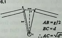
| (6.1) |
4 But we know from Equation 3.3 and Equation 3.4 that gap and dip both diminish as the dip angle diminishes; and we know from Equation 3.2 that the dip angle diminishes as the number of struts around a great circle or a lesser circle increases. So increasing the number of struts around a circle—which is what we are doing when we increase the frequency—both shortens the gap and diminishes its depth.

6 This means (Diagram 6.2) that as we increase the frequency 6.2 each gap narrows, and as it does so the strut that passes beneath it moves outward from the center, closer to the surface of the sphere. If it moves outward until the depth of the gap is just equal to the thickness of the struts, it will be so situated as just to touch the bottom edges of the upper struts (Diagram 6.3). By this time the gap will be extremely narrow, and a very little extension of the ends of the upper struts will ensure that they too will touch.
7 Let us suppose that the system is made.of wood. We can cut the ends of the upper struts so they meet squarely, and we can bevel the upper edge of the lower strut so it fits snugly under them. We may also remember from Chapter 3 the option of replacing the large tensional diamond by a little sling that follows the lines of the dip. Diagram 6.3 shows it embedded in the wood, but it may easily be replaced by a couple of bolts. Tightening the nuts will draw everything together.
8 Now, note carefully: When we commenced this process, the rest of the system was tending to pull all three components apart. Now that they are touching each other, this is still true. The two upper struts are not in compressive contact: if released, they would pull apart. And they are not resting on the lower strut: if released, they would move outward and away from it.
9 The bolts and nuts are quite literally serving to draw the elements together. They are performing the function of the tension members in the original Tensegrity.
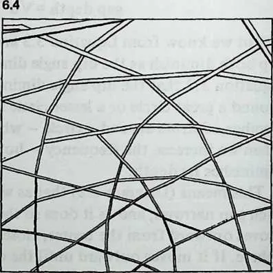
10 Repeat this throughout the domical structure, and we have an array of interlaced polygons, weaving alternately above and below the polygons they cross, and bolted at the crossing points. They outline pentagons, hexagons, and triangles and make a sturdy domical structure with no noticeable flexion (Diagram 6.4).
11 Having developed this structure from Tensegrity principles, we know about the tensile forces that are holding it together. Trace- able through the bolts and the wooden beams, they form a tensional continuity, resembling the surface tension of a liquid sphere in being concentrated on the outer surface of the polyhedron.
12 But a casual observer of the structure would soon commence studying the joints, and seeing what is diagramed in Diagram 6.3 he would suppose that the bottom member was bearing the weight of the upper ones. He would suppose that the structure was in compression, like a frame house, and that the bolts functioned merely as do carpenter’s nails, to prevent lateral slippage. He would therefore form a wholly erroneous idea of the system’s dynamics.
14We have now reached the governing center of geodesic-dome design. The structure is lifted outward by a hidden tensional system. It resembles a contained explosion, like a balloon: compressive out-thrusts held in a tensile web, with this difference, that the forces pulling outward are also coming from the web. The structural members are not falling in together, nor in any important way leaning on one another.
15 However variant geometries and connecting systems may modify this account, it remains the first principle of geodesics.
6.1 Numerical Example
16Some scratch-pad figures may help the reader visualize possibilities. An eight-frequency subdivision of the icosahedron ( icosa) is shown in Diagram 6.5, with the Tensegrity strutting indicated in heavy lines. Four struts span two triangles; since ten triangles girdle the icosahedron, the structural circles will be -gons, and the dip angle 180°/20, or 6°. Gap is 0.00274, dip is 0.026, and by Equation 6.1 gap depth is 0.026. (At high frequencies, gap depth is very nearly equal to dip). Radius is 4.79. Lesser circles , being nearer the equator, will be slightly larger and will have longer struts than lesser circles , but for the sake of a quick estimate we can assume an average strut length. Let’s put it at 8 feet, a , larger lesser circles , smaller lesser circles handy length in building with two-by-four lumber. We get a radius of , or 38 feet: say a 75-foot sphere. The gap will be a mere quarter of an inch. The interesting parameter is its depth, , or 2 1/2 inches. Since a so-called two-by-four is about inches, two-by-fours turned edgeways will touch with an inch to spare for notching or beveling. We can bolt the whole thing together.
17 Buckminster Fuller erected such a framework about 1956, in Carbondale, Illinois. Since it followed a different geodesic geometry, it had fewer and longer members than those we have calculated, but the two-by-fours were bolted together, crossing under and over, just as we have described. It was very, very strong. Since Fuller had already by that time erected numerous geodesic domes of the familiar omni-triangulated variety, this 72-foot model constituted, as it were by afterthought, a demonstration that geodesics is in fact a special application of Tensegrity.
18 We now move on to geodesics proper: the generation of omnitriangulated, quasispherical, tensile-compressive free-span structures.