7 Great Circles
1A geodesic dome is sliced from one of the complex polyhedra we were learning to design in Chapter 5. It has a large number of triangular faces, all approximately—but not quite—equilateral. The struts that bound them follow the paths of great circles, sometimes complete, more often interrupted. The cohesion of the whole, like that of a Tensegrity, is both compressive and tensile; it is helpful to imagine the tension system running along the outer surfaces of the struts, which are simultaneously loaded in compression.
2 As we saw in Chapter 1 (Diagram 1.1), tensile forces in post- and-beam construction run along the under edges of the beams, resisting central sag. In Tensegrities, on the contrary, tensile forces surround the system, hauling the vertices outward and so removing the need for posts. The first large geodesic structure (Robert W. Marks, The Dymaxion World of Buckminster Fuller, Carbondale: Southern Illinois University Press, 1960, figs. 0.19-0.21) retained separate tension members, running to every vertex from pegs jutting from neighboring vertices; since then it has been clear that at moderate frequencies the tensile cohesion inherent in the upper surface of the strut has ample mechanical advantage, and in most domes the tensile members are inextricable from the compressive, concealing from the casual eye the crucial importance of tension.
3 It is evident that the hub systems, as well as the struts themselves, must resist pulling forces as well as pushing forces. When heavily loaded, either by its own weight or by an imposed stress, a geodesic system will tend to pull apart at some of the hubs.
4Again, make a model before proceeding further. Diagram 7.1 shows a simple 3v.icosa; connections are flexible; clearly the strength is derived from geometry, not joinery.
5Experiment.
6Try removing one strut.
7Try removing one connector.
8Note that at exactly twelve points, evenly distributed about the sphere, five triangles meet at a vertex. Elsewhere, the number that meet is always six.
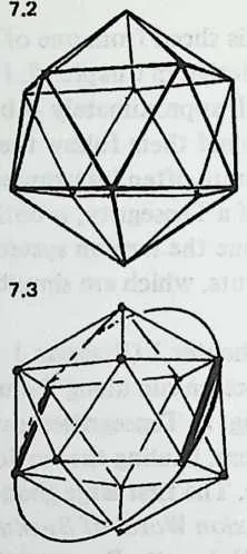
9Make an icosahedron (Diagram 7.2) with twelve more connectors and twenty struts of equal length. Note the five triangles meeting at each vertex. Observe the resemblance to the 3v icosa sphere.
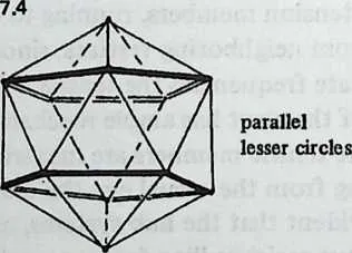
10Finally, observe the circle patterns. The five-way vertices are called pents (after the pentagons that surround them). From each pent center radiate portions of five great circles. Each has its center at the center of the system. Each sets off on a 360° circuit, of which it completes about 63.5° before bumping into another pent center (Diagram 7.3).
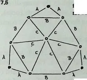
11But if you follow the lead of any pentagon edge, you can trace a circuit clear around the sphere. This is a lesser circle; its center is not at the center of the system. They girdle the sphere in parallel pairs (Diagram 7.4), like the Tropic of Cancer and the Tropic of Capricorn.
12It is natural to think of cutting the sphere along one of these lesser circles to get a tall ora shallow dome. Try it by unfastening connectors. Your first discovery will be that the dome does not sit quite flat: the struts in the lesser circles are almost, but not quite, coplanar. Obviously, the lengths of struts leading to the lesser circle could be adjusted to get a level truncation plane. That’s something design must take into account.
13The next discovery to be made from a dome model is that the perimeter wobbles. Away from the perimeter, the structure resumes its rigidity. As in a Tensegrity, tensile circuits must be completed. A dome design is not completed until its lower edge is fastened to the earth. It is ultimately the inelasticity of the earth itself that the tensile network transmits through the structure.
14 The next step in investigating domes and great circles is to make a companion model based on the octahedron instead of the icosahedron. Diagram 7.5 gives data. Comparing the two models, we notice several things immediately.
16The octa uses fewer struts and connectors, and has fewer faces.
- The octa is much less smoothly spherical This derives from the fact that an octahedron is a poorer approximation to a sphere to begin with. Its sphericity can be improved by raising the frequency. A octa has a component inventory comparable to that of the icosa (300 edges, 102 vertices, 200 faces) and is comparably smooth in curvature.
- Instead of the icosa’s twelve pents, we find six squares, corresponding to the six vertices of the parent octahedron.
- Like the icosa’s great-circle arcs from pent center to pent center, the octa has great-circle arcs running from square center to square center. But instead of being intercepted at the next square center, each meets a partner at 180° and in effect continues straight through. Thus every octa, regardless of frequency, has three mutually perpendicular great circles outlined by its struts, making natural hemispherical truncation planes. (Icosas display hemispherical great circles at all even frequencies.1)
28Like the icosa, the octa also displays wobbly lesser circles. Truncation at other than hemispheric intervals will require adjusting strut lengths to make one of these lesser circles planar.
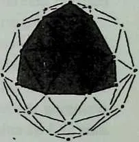
30 It is clear that certain characteristics of the parent polyhedron carry over into its geodesic derivates. The icosahedron has no vertex-to-vertex great circles, and neither has any of its geodesic subdivisions. The octahedron on the other hand has three, and so have its breakdowns. The icosahedron has twelve vertices where five triangles meet, the octahedron six vertices where four triangles meet; the same is true of their frequency subdivisions. (In either case, all other vertex points are hexagonal, by-products of the three-way grid.) Most important, an observer at the center of the system would look in the same directions to see the same pent points (icosa) or square points (octa), regardless of frequency. We shall later be deriving important consequences from this fact.
7.1 Great-Circle Systems
32We can now look more closely at the relationship between polyhedra and great circles. The most vivid look is prepared for by making an icosahedron of cardboard (twenty equilateral triangles, about inches to a side, glued together at the edges with contact cement).

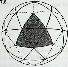
34 Press fingertips to a pair of opposite vertices and turn the icosahedron on the axis your fingers define. If you now imagine it spinning rapidly, you can see where the equator of spin would lie. If you next move the fingertips to a new pair of vertices without changing the icosahedron’s orientation in space, it acquires a new axis and its spin will trace a new equator, inclined to the first. If you keep this up till you have used all six pairs of opposite vertices, you will have six equators symmetrically intersecting one another. Diagram 7.6 shows all of them and shows how they symmetrically subdivide the faces of the spherical icosahedron. This is the family of the six great circles.
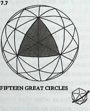
35 We next repeat this exercise, using mid-edge points for the poles of spin. There are fifteen pairs of opposite edges, and rotating the icosahedron between fingers pressed to the midpoint of any pair will describe an equator like the one in Diagram 7.3, cutting through two pairs of triangles and coinciding with two edges. By the time we have used all the axes of rotation we have located the fifteen great circles. Diagram 7.7 shows how they outline every icosahedral face, and also slice through every face three ways.
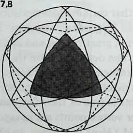
37 There is one more great-circle family, which we locate by using mid-face points for the poles of spin. (A triangle’s mid-face point is located by joining each vertex to the midpoint of the opposite side. It is two-thirds of the way down each altitude and is also called the triangle’s center of gravity.) The icosahedron has 10 pairs of opposite faces, and spinning it successively on an axis passing through each pair gives us the ten great circles. Diagram 7.8 shows how they are located. If we follow any one of them along its successive crossings of icosa triangle edges, we shall see that it repeatedly leaves the midpoint of an edge to cross the next edge at right angles.

39 So the icosahedron has three families of symmetrically placed great circles, totaling , or .
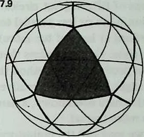
40 We can now try some combinations. Start with the six great circles. Next outline the faces of the spherical icosa; we do this by using portions only of the fifteen great circles. Diagram 7.9 shows the result: a geodesic breakdown. If the vertices were joined by chords instead of arcs they would diagram a perfectly useful structure. They would be of two different lengths, and the longer ones would follow the six great circles. The shorter members, outlining icosa edges, define portions of interrupted great circles. The subdivisions tend to run in the same directions as the icosa edges, and we see at once why any emz-frequency subdivision of this general design will yield equators: they are the six great circles.
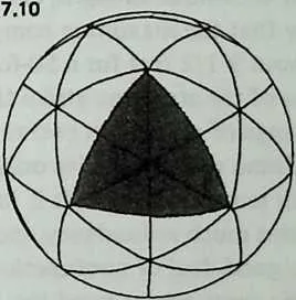
42 We now try something else. Commence with the fifteen great circles, and this time remove the portions that outline icosa edges, leaving everything else. This gives us (Diagram 7.10) another breakdown, this time with no complete great circles at all. (By adding four members, to complete two icosa edges, you could make an equator that coincided with any one of the fifteen great circles. The new members would cut four triangles in half.) This kind of breakdown, cutting perpendicularly across icosa edges that are no longer present, is called Class II. (The breakdown discussed first is Class I.)
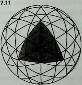
44 We may remember that the ten great circles also cut icosa edges perpendicularly, and try inserting them. Diagram 7.11 shows why this is unsatisfactory. It approximates a breakdown, but the triangles are of markedly different sizes, and some of them are excessively isosceles.
45 Still, we can understand why, in the pioneer days of geodesics, this sort of subdivision was the first to be explored: it promises access to the largest inventory of great circles, potentially twenty-five. Breakdowns of this general configuration were at first called regular, later triacon (after the rhombic triacontahedron, whose contours it suggests). It proceeds by joining each vertex of a tri-angular icosa face to the midpoint of the opposite edge (which gives portions of fifteen great circles) and running additional lines of subdivision more or less parallel to these (which with luck will pick up portions at least of ten more). In the finished artifact only this grid remains: the icosa edges themselves disappear. Later investigation produced the method that yields subdivisions parallel to triangle edges. Being an alternative to its predecessor it was called the alternate breakdown, a name that has stuck, though ‘‘Class I’’ is more formal.
46 In what we may call the prehistory of the art, there were no breakdown systems at all. Buckminster Fuller’s first experimental domes were simply sets of icosahedral great circles, made of short chordal members bolted together. All thirty-one great circles made a structure of enormous strength, and they intersected one another so frequently that the maximum component length was never excessive (about 9 1/2 feet for a 50-foot-diameter structure). Still, disadvantages of the structure strike the eye: component lengths vary over a range of more than two to one, and so does vertex population. Some vertices receive only four members; others are cluttered with ten and twelve.2 It is intuitively obvious that such a system contains much redundancy and (putting the same thing differently) a good deal of nonfunctional weight.
47 Omitting six great circles eased the clutter somewhat; there were families of structures with twenty-five great circles. The next step, obvious in retrospect, was perhaps the most difficult to conceive: interrupting fifteen of the twenty-five great circles by removing members that outlined icosa faces (Diagram 7.10), and extending members that had terminated on an icosa edge to reach into the next triangle. All vertices were then sixes and fives, and strut-length variation was just under 2 to 1.
48 The system was how about to take its leave of what seems to us, decades later, a naive dependence on inherent great circles. (The name geodesic dome preserves the memory of that initial dependence.) It is obvious that more members can be introduced, parallel to the ones we have. This gives rise to the concept of frequency subdivision. It also permits the shorter component lengths we shall heed for very large structures. It is also obvious that by tinkering with the geometry we should be able to bring strut lengths closer to equivalence. The systems of geodesic breakdown commence at this point.
7.2 Octahedral and Tetrahedral Great Circles
49The octahedron too has three families of great circles, which the same experimental method will locate. The three vertex-to-vertex axes yield three great circles, which coincide precisely with the octahedron’s edges. Mid-edge to mid-edge axes yield six great circles, of which three appear on any single face, coinciding with its medians. The axes passing through opposite pairs of mid-faces yield four great circles, of which any face exhibits parts of three, joining the face’s midpoints. So the octahedron has great circles, of which any face is bounded and crisscrossed by 9.
50 If we design a geodesic sphere or dome by subdividing an octahedron, this set of thirteen comprises all the complete great circles we can possibly obtain. All others will be interrupted. Any Class I subdivision yields three, the ones bounding the octa edges. (Hence all Class I octa subdivisions have natural equators.) Any even-frequency Class I octa subdivision has these three and also four more (look back at Diagram 5.2). So all even-frequency Class I octa subdivisions contain seven complete great circles each. But as long as the lines of subdivision run parallel to the octa edges, there is no way to incorporate the remaining six great circles at all. Class II subdivision gives us access to these, but loses the other seven.
51 The tetrahedron, in this as in many other respects, is bafflingly economical. It has no opposite pairs of vertices. Each vertex is opposite a mid-face, and joining these unmatched pairs by axes we obtain four equators of spin, four great circles, of which any single face exhibits parts of three. Axes through pairs of midedge points yield another four great circles, of which each edge again exhibits parts of three, joining its mid-edge points. That is all.
52 An even-frequency Class I subdivision will display the first set, and if the frequency is divisible by 4 the second set will be present, as well. Class II subdivisions with frequencies divisible by 4 display the second set of great circles if they follow Method 1 (see Chapter 10) but none at all if they follow Method 3.