14 Truncations
1So far we have been accepting symmetry systems just as they come from the mathematician’s repertory. We made certain choices: the rest was law. We chose a polyhedron, we chose a frequency and a breakdown, we chose floor and roofline cross-sections with an expansion and an exponent for each; having chosen, we accepted what came out of the calculator. It is now time to contemplate a few interventions, which modify the crystalline symmetry of the result to make it more useful. In particular, we want to be able to slice our complex polyhedron at will and make it sit flat; we need to design truncation planes into it.
2 A few of these are inherent, and always equatorial. The octahedron has natural equators, the inherent great circles, and any breakdown preserves some of them. Complete icosahedral great circles are preserved by any even-frequency Class I breakdown. Class II icosa great circles are tantalizing: they are twice interrupted in their circuit around the sphere, and they lie flat only when the sphere is tipped so that an edge, not a vertex, is at the zenith. To get at them will take special handling: we’ll come to that.
3 If we want something other than a hemisphere—in short, a lesser-circle truncation—vie find that no combination of breakdown and frequency will give it to us. We shall have to tamper.
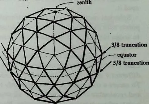
4 There are two main ways of tampering. One is to devise a truncatable breakdown, which supplies crisscrossing lesser circles throughout the system. Any of these will then serve as a truncation plane. Diagram 14.1 gives a rough idea. In its raw state the icosa is girdled by twelve approximate lesser circles, running in pairs like the Tropic of Cancer and the Tropic of Capricorn, parallel to six imaginary equators (the six great circles, which the breakdown does not incorporate). They are so nearly level that many builders have simply chosen to pretend they were truncation planes, and have shored up the wobble with blocks (see Lloyd Kahn’s Domebook 2 [Bolinas, Ca., Pacific Domes: 1971] p. 24). Truncatable breakdowns level all twelve of these circles off, giving the builder a choice of two genuine truncation planes, at approximately and of the sphere’s volume.
6 This attractive method leads to a couple of interrelated difficulties. Tampering with the overall geometry can lead to poor distribution of spherical excess; avoiding that can lead to surprisingly wide variations in strut length. Some of the earliest truncatable designs incurred the first of these difficulties: the pentagon vertices were excessively peaked, leaving the rest excessively flat. Other solutions trade asymmetry of spherical excess for asymmetry of member length, chord factors varying as much as 45 percent (vs. about 17 percent for the normal 3p). Truncatables do not need to be unhandsome: an especially fine roofs the religious center at the Edwardsville campus of Southern Illinois University, strut lengths varying in a sequence so elegant it looks more like an aesthetic modulation than an engineer’s contrivance {Architectural Forum, January-February, 1972:86, fig. 5).
7 Still, for many purposes the second main solution to the truncation problem is preferable. It amounts to leaving most of the design alone and inserting just one truncation plane where we need it.
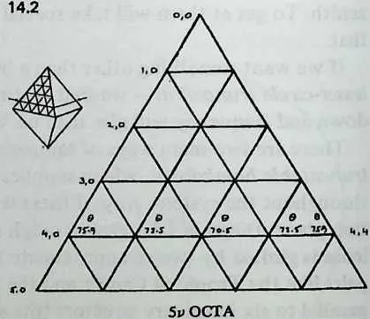
9 Spherical coordinates make this extremely simple. Since all points with the same 6 lie on the same lesser circle, we have only to assign the same to contiguous points and a truncation plane will pass through them.
10Example 6Diagram 14.2 shows one face triangle of a 5v octa, Class I, which we propose to truncate along the line 4,0-4,4. Three different values appear on this line, 75.9638, 72.4516, 70.5288. To secure a truncation plane we have only to make them all equal and recalculate the chord factors for all struts connected to the points whose location we are changing. We can select one of these values—say, the edge one—and make the others like it, or we can arbitrarily bring everything to some convenient norm—say, 72. In any case, since the bottom row (5,0-5,5) will be discarded in the truncation process, and mirror symmetry takes care of the right half of the system once we have determined the left, this means, at most, recalculating just 6 values: 3,0/4,0; 4,0/4,1; 3,0/4,1;/4,2; 3,1/4,1; 3,1/4,2. Everything else is left as it was.
11 The icosa as usual requires a little more care. What Fuller calls the icosacap (the five triangles around the zenith) makes so shallow a saucer we are unlikely to want to use it by itself, let alone truncate it. Icosa truncations will cut through the 10 triangles that girdle the sphere’s waist, the #2 triangles in the diagram we took into account with ellipsoids in Chapter 13.
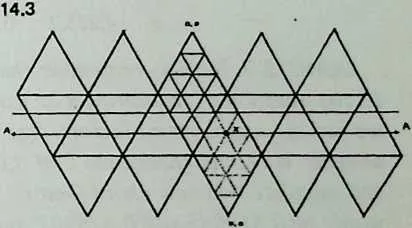
13 Diagram 14.3 shows a Class I icosa opened out to display all twenty face triangles. A likely plane of truncation would follow line , passing below the equator to give the so-called truncation. Inspecting the Class I icosa tables, we see at once why amateur builders have gotten by with this truncation as it stands, using blocks to shore up the discrepant places: along the line 4,1-4,3, which is where we are cutting, the 0 values luckily differ by only 2/3°. To achieve a perfect truncation, we have only to raise the 9 of point 4,2 from 79.1877 to 80.1169 and refigure the associated chord factors. (We might elect instead to leave 4,2 alone and bring 4,1 and 4,3 into agreement with it, but then we should also have to alter 5,2 and 5,3 on the down-pointing adjacent triangles to make them match. It saves work to leave edge points alone when we can.)
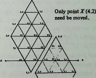
15 So many icosa domes with uneven -sphere truncations have been built from Domebook data that full data for a smooth cutoff may be interesting. The basic chord factors are:
| a | 0,0/1,0 | 0.348615 |
| b | 1,0/1,1 | 0.403548 |
| c | 1,0/2,1 | 0.412411 |
| d | 1,0/2,0 | 0.403548 |
16 These are used for the five top (icosacap) triangles. They are also used for the #2 triangles that point downward below them; for a truncation the down-pointing triangles are completed as far as . It is on the up-pointing #2 triangles flanking them that we move to its new position , making its equal to that of and (that is, ). With this we obtain new chord factors for and :
| e | 4,2/4,1 | 0.412703 |
| f | 4,215,2 | 0.398734 |
17 These are used only for the members around the truncation perimeter; for the rest of the dome we use regular chord factors.
18 If we wanted a 3/8 truncation instead of a truncation, study of the diagram shows that we should use a revised chord factor for instead of . It is
| g | 4,2/5,2 | 0.426214 |
19Example 7We may remember that we left dangling in Chapter 13 the question of truncating a 2v icosa Class II ellipse for which we had calculated chord factors. One way of doing this is now obvious. We could change the 0 of 3,0 to agree with that of 3,1 and calculate two new chord factors, 3,0/3,1 and 2,0/3,0. These would be 0.613085 and 0.378907, respectively. The latter figure provides for some rather stubby structural members, but the dome will sit flat. It will also curve in slightly near the bottom, since the truncation 6 (100.8123170) lies below the 90° line.
20Or we might move both 3,0 and 3,1 up to 90° (their coordinates would be 0,90 and 36,90, respectively) and refigure four distances: 2,0/3,0; 2,0/3,1; 3,0/3,1; 2,1/3,1. This would truncate the ellipse precisely at its zone of maximum radius, though all the base members would be somewhat short.
22 A better way to truncate Class II spheres introduces us to a new principle:
14.1 Truncation by Rotation
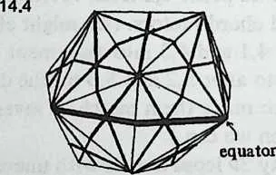
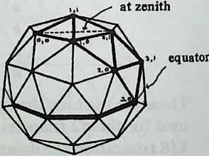
23While we were struggling with the last example, the reader may have been wondering what happened to the great circles to which Class II breakdowns give access. The answer is that they are ready and waiting, but not while a vertex is at the zenith. Diagram 14.4 shows this; if we rotate the structure till an edge is on top we obtain equatorial great circles, twice interrupted in their circuit of the sphere.
24 Since the whole coordinate system hangs together, what we need is a way of rotating it as a whole until the midpoint of an icosa edge moves to the zenith.
25 The midpoint of a Class II icosa edge is . This is listed in the Chapter 21 tables as Point 2,1 of a Class II breakdown. If this isn’t clear, consult Diagram 10.6, which shows the icosa edge passing down the middle of a Class II triangle. We need a way of telling what the other points become when this point becomes 0,0. We use the rotation formulae1, which tell us that when 0,0 moves to 0,0, then will move to:
| (14.1) |
26 and will move to:
| (14.2) |
27 Let us try this out with a Class II sphere. The Class II Method 1 tables give us the following coordinates for an icosa:
280,0 | 290 | 300 |
311,0 | 320 | 3337.37736811 |
341,1 | 3572 | 3637.37736811 |
372,0 | 380 | 3979.18768300 |
402,1 | 4136 | 4263.43494883 |
433,0 | 440 | 45116.5650512 |
463,1 | 4736 | 48100.8123170 |
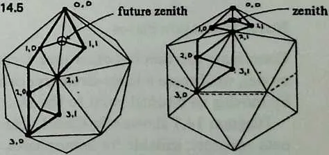
50 We can see from Diagram 14.5 that when a structure is rotated in the manner we contemplate, 3,0 will lie on the equator and 3,1 somewhere above it. Clearly these are the only points that will have anything to do with a truncation, so we ignore all the others and feed these two into the rotation formulae. We obtain, if we use 36 for and for , the following new coordinates:
51523,0 -31.717474 90
53. 3,1 0 69.0948426
54 We will have a truncation if we create a new vertex, 0,90, for the center of the diamond we are slicing and join both these points to it. The point can be called , and the chord factors will be:
55563,0/x 0.546533
573,1/x 0.362843
58 This will give us an edge-zenith sphere with a truncation utilizing one of its inherent great circles. The regular chord factors will take care of all the other structural members.
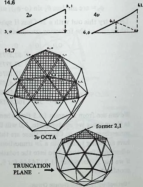
59 This particular problem could be solved in perhaps less time geometrically. But at higher frequencies than , coordinate rotation is the way to solve Class II truncation problems. The diamond being sliced by the truncation plane has always the same boundaries; at higher frequencies we are simply inserting more new members (Diagram 14.6).
60 It would be quite possible to handle the Class II ellipse in the same way. We should first rotate all the coordinates, then obtain radii, chord factors, and truncation members. The method is not recommended for three reasons:
- 1.
- It is a great deal of work.
- 2.
- An ellipsoid with an edge zenith is an awkward looking structure.
- 3.
- By the time we have finished the coordinates have undergone so much manipulation that rounding-off errors make the fifth place of the chord factors wobbly.
14.2 Novel Truncation Planes
61Coordinate rotation has other uses. Occasionally, examining a model, we discern a lesser-circle truncation plane made available by moving an unusual point to the zenith.
62 Diagram 14.7 shows a Class I octa sphere. It has the usual octa equators, suitable for hemispheres. Rotating a model, however, till the central vertex of an octa face (2,1) is at the zenith, we notice two irregular lesser circles, resembling those of the icosa.
63 Truncation along the lower one of these is ah interesting possibility. The resulting structure is somewhat taller than a hemisphere and has three quadrangular skylights symmetrically disposed around the zenith.
65 Our first step, clearly, is to make the coordinate system correspond with the way we are viewing the model, by moving 2,1 to the zenith. We won’t, of course, be calculating the result of moving every point—just the ones that will be affected when we straighten out that lesser circle. Diagram 14.8 shows the situation. Rotating the sphere toward the eye until the 2,1 point on the far side arrives at the zenith, we discover that the array on the face nearest us has moved down to the desired truncation plane, which is irregular because 2,1 is misaligned with its neighbors. To straighten out the truncation plane we have only to equalize the values these three points assume in their rotated position. We shall be altering the occupied by a shifted 2,1, and shall need its revised distances from a shifted 2,0 and a shifted 1,0. So we need rotate only these three points.
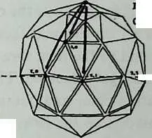
67 The coordinates of the point on the far side of the sphere, which we propose to move to the zenith, are 225, . (Its is the same as that of 2,1, and its 0 is 180° greater.) Inserting these figures into Equation 14.1 and Equation 14.2 along with the coordinates of the three points to be recalculated, we obtain their new coordinates:
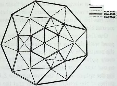
77 As we might have expected, the new of 2,1 is relatively close to that of 2,0 (and by symmetry, of 2,2). To effect the truncation, we equate them, taking the edge-point value (104.9632174) as the norm. Using this new value for 2,1 we obtain the following revised chord factors:
78792,0/2,I 0.674981
801,0/2,1 0.607864
81 Being very careful to notice what goes where (Diagram 14.9), the builder how employs these values in zones adjacent to the truncation plane and constructions a rotated/truncated octahedron with 2,1 at the zenith. The disposition of the square skylights is pretty.
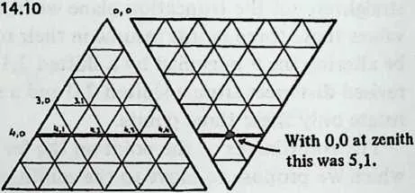
82 For a more tightly woven mesh, we might double the frequency of this. For a we would straighten out the row 4,0-4,1-4,2-4,3- 4,4. Mirror symmetry permits us to do this by attending only to and 4,2 plus the points connected with them, 3,0 and 3,1. But (see Diagram 14.10) the 2,1 point on the adjacent, down-pointing octa face is now located on the truncation plane and must be aligned with its neighbors. When the octa was in its unrotated position, this was 5,1 on the next face clockwise; take the 0 of 5,1, add 90° to get round to the next face, and relocate the result like the other points that get relocated. Then give it the same 0 as the rest of the truncation plane and obtain new chord factors.
83 The square windows on the version will be smaller than on the . Should we prefer the larger size, we could omit 1,0 /1,1, 1,0/2,1 and 1,1 /2,1, then figure 0,0/2,0 and 2,0/2,2 as a single long chord.
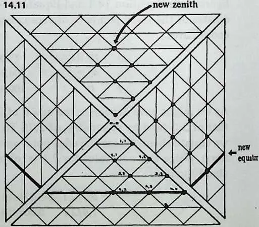
84 Should we like this well enough to attempt an elliptical version, we should need to move more points: Diagram 14.11 shows where they are located.
14.3 Zenith Altitude and Floor Radius
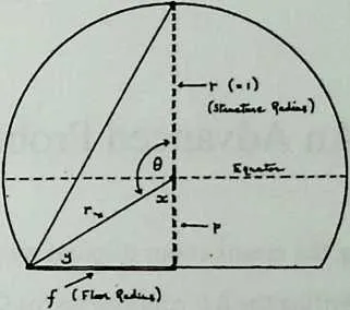
85Having truncated a dome we shall want to know how high its zenith point will be and how large its floor. Diagram 14.12 shows the derivation of two very simple formulas. The zenith altitude is simply:
8687altitude = - cos 0, [Eq. 14.3]
88 and the floor radius is given by:
8990floor radius = sin 0. [Eq. 14.4]
91 In these expressions is of course the 6 of the truncation plane, and for spheres = 1. So for the rotated octa discussed previously, the zenith altitude is 1 - cos 104.9632174, or 1.258199, which means we have gained 25 percent more zenith headroom than a hemispherical truncation would have permitted, and the floor radius is sin 104.9632174, or 0.966092. The floor area is approximately , or 2.932153 (‘‘approximately’’ because we are pretending a polygon is a circle); since the floor of a hemisphere (radius = 1) would be 3.141593, we have gained our extra headroom at a cost of 6.66 percent in floor area.
93 Should we be analyzing elliptical contours, we should need slightly more complicated expressions: if is the radius of the zenith point, and is the radius at the truncation plane, then
9495altitude = rz- rt cos 6. [Eq. 14.5]
96floor radius = rt sin 6. [Eq. 14.6]
97 If the floor is itself elliptical, there will be numerous values of ; we should probably be interested in the largest and the smallest, which would give us the length and width of the floor.